Electromagnetic contactors (KM), widely used in electrical engineering, are special devices capable of switching large currents. A feature of these power devices is the ability to control load currents by means of circuits that are not structurally related to the switched load. To understand the essence of the processes occurring in the contactors, you should familiarize yourself with the principle of their operation.
Design and principle of operation
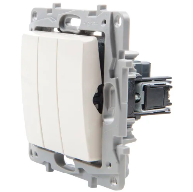
- Power contacts that supply current directly to the consumer or to the electrical installation.
- A set of springs used as downforce in a structure.
- Plastic traverse connected to a movable armature and used for attaching contact jumpers.
- An electromagnetic coil that controls the position of the crosshead and changes the state of the contactor with its help.
The switched contacts themselves are made of copper alloys, which ensures high electrical conductivity and reliability.
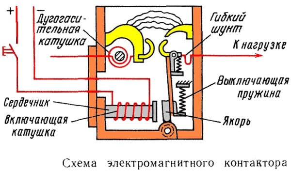
After applying voltage to the electromagnet, the armature shifts downward under the influence of the field and attracts the traverse with contacts in the same direction. The movable parts of the contactor fixed on it are closed with fixed spots, creating a flow circuit for the current. When the voltage is removed from the electromagnet, the armature returns to its original state under the action of the spring and the contacts open. For emergency shutdown, it has a special push-button switch installed in the additional switching chain.
The principle of operation of a switching device helps to understand how contactors differ from relays or any other switching device: relays and contactors are designed for currents of different magnitudes, differing tens and even hundreds of times.
Differences between contactors and magnetic starters
In terms of their functionality, these two devices are no different. They allow switching power circuits and include from two (single-phase contactor) to four "powerful" contacts. The difference begins to appear when considering the following features of these devices:
- dimensions and weight of the device;
- contact switching zone design;
- direct appointment.
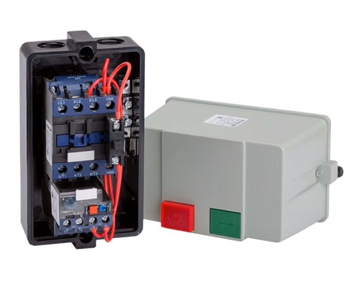
Magnetic starters are commonly referred to as "small contactors" to indicate their difference in size and weight. But the matter is not limited to this, since the fact that the contactor pairs have special chambers for extinguishing the arc is not taken into account. Thanks to these elements of the housing, the electrical contactor does not have one as such, it itself is installed in rooms locked on a key without access by unauthorized persons.
The power contacts of the magnetic starter are covered under reliable plastic covers, but do not have extinguishing chambers. In this case, the devices themselves are installed in a circuit with a limited value of the switched current. Hence the third difference between devices, which consists in their purpose.
The three-phase contactor can be installed in any power line, providing reliable connection and disconnection of any load.Magnetic starters are traditionally used for switching control circuits of induction motors and are capable of starting them in various modes, including reverse.
Marking and types
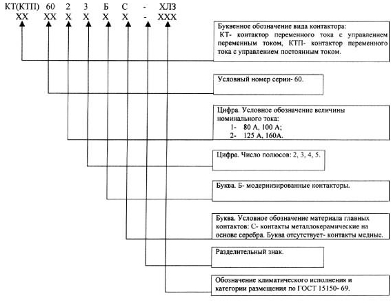
To distinguish between individual models of three-phase and single-phase contactors, the following symbol or marking is used: KT (KTP) - X1 X2 X3 X4 C (A or B) X5. They are decrypted as follows:
- the first icon corresponds to the series number (60 or 70);
- the second - the dimensions of the contactor from the following row: 0, 1, 2, 3, 4, 5, 6№;
- X3 is the total number of poles (2, 3, 4 or 5);
- X4 (letters A, B or C) indicate the specifics of the series in terms of the features of the switching contacts;
- X5 is an indicator of climatic performance: U3, UHL or T3.
Various types of contactor devices are classified according to the following criteria:
- available protective equipment and operating voltage (220 or 380 volts);
- contact actuation method;
- the number of contacts in the power group.
Almost all contactor models are equipped with solid-state thermal relays that open the load circuit in case of overcurrent, like a circuit breaker release. After disconnecting the contacts and cooling the protective circuit breaker, it is necessary to re-enable the device to work. In accordance with the supply voltage of the device itself, their coil can be designed for both 220 and 380 volts.
In practice, there are DC contactors, so called in accordance with the type of control action. A typical example is a 12 Volt DC contactor.
The nature of the operation of contacts

By the nature of the closure, the following types of contactors are distinguished:
- Direct connected devices with only one group of power contacts. They work only for switching on and off and have overload or short circuit protection.
- Reversible instruments equipped with two groups. With their help, it is possible to correct the circuit for switching on the load, changing the sequence of the phases, for example.
- Devices with a limited set of switching: only for closing or only for opening.
The latter type is used when it is necessary to control two electrical installations in antiphase. In this mode, one of them is connected to the line, and the second is de-energized synchronously with it.
Number of contacts

By the number of contacts of the power group, the devices are divided into the following types:
- 2-contact devices for single-phase circuits;
- 3-contact devices that switch only phase groups, zero on them does not start;
- with four or more contacts in power groups.
A switching group is understood as a set of normally closed or normally open contacts.
The latter type of products is used extremely rarely, only in special connection schemes.
When considering the varieties of devices of this class, one cannot fail to mention the modern counterparts represented by AC thyristor contactors. In these devices, purely mechanical contacts are replaced by electronic transitions characteristic of semiconductor contactors.
Self-connection
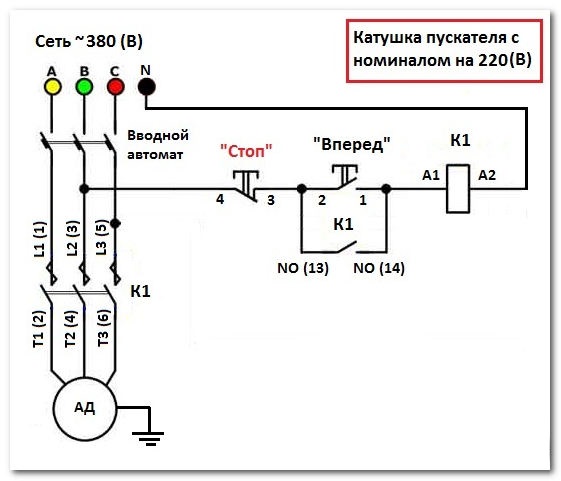
Before installing a single-phase contactor in a cabinet on a DIN rail, and connecting it yourself, be sure to pay attention to the presence of two chains in the circuit. One of them is power, and the second is signal, through which it is possible to control the operation of the device. For this chain to work, after installing the device in the cabinet, you will need to supply power to its contacts, traditionally designated as A1 and A2. They are supplied with exactly the voltage for which the contactor coil is designed.
The switched power circuit is connected to the terminals located at the bottom of the device and usually indicated by the symbols T1, T2, T3. Thanks to their presence, it is possible to implement a three-phase contactor wiring diagram.With this inclusion, you can control the power circuits that are part of any power generating unit, including wind and diesel generators. The type of voltage they generate is also irrelevant.
Major malfunctions
Possible breakdowns of contactors include failure of the magnetic control coil, as well as burning and failure of the switching contacts themselves. In the first case, the only possible way out is to replace the coil with a new, working sample. If the contacts burn, you can try to restore them by slightly cleaning the damaged areas, first with a file, and then with a fine sandpaper. However, such a "cosmetic" operation is not a way out. Sooner or later, the user will have to replace the burnt contacts with new (backup) or samples taken from another device.