The specific operating conditions of the toilet room presuppose the presence of effective ventilation in it, which is not provided by the system of ventilation ducts (shafts) built into the walls of the building. It is possible to improve air exchange in the room by placing a special fan in the exhaust hole of the shaft, the installation of which (subject to certain conditions) can be done independently. In this article, you can familiarize yourself with the features of choosing a suitable fan product, as well as with the procedure for installing it in the washroom.
Features of the operation of the ventilation device in the toilet
A distinctive feature of the fan in the toilet is the frequency of its operation, determined by the need to ventilate the room only at certain intervals (during and after a visit). This explains the special approach to the procedure for installing the device, taking into account the following operational requirements:
- the presence of an electrical connection to its location in the hatch of the ventilation shaft;
- the need to prepare a special connection diagram;
- Convenience of manual control of the fan operating mode;
- noiseless operation of the system located in the immediate vicinity of the habitat.
To fulfill all these requirements, you will need to carry out a whole range of activities that involve:
- a competent choice of a fan model suitable for the type and characteristics;
- its direct installation in the shaft hatch;
- preparation of the connection diagram and control of the device operation modes;
- laying of electrical wiring to the place of its installation, taking into account the requirements of the PUE;
- connection to an existing electrical network.
In the following sections of the article, we will consider the procedure for installing a fan for a toilet in more detail.
Selecting the type of fan device
Before purchasing a fan suitable for working in a toilet, you should familiarize yourself with existing product modifications, which are divided into axial, radial and centrifugal designs by their design. Each of these types of ventilation devices can be mounted both on the wall and on the ceiling.
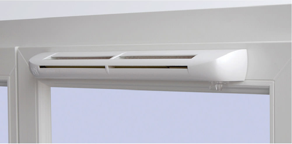
According to most experts, it is most convenient to install axial mechanisms in the toilet and bathroom, the basis of which is a multi-blade propeller fixed on the axis of the electric motor. Air intake in such a device, the body of which is usually oval, is carried out through its front part, protected by a special plastic panel. When buying a suitable model of an exhaust device, be sure to pay attention to the noise level it creates during operation, which must be indicated in the product passport. The approximate value of this indicator should not exceed 40 dB.
On-site installation
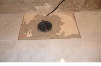
In accordance with the previously considered procedure for installing a fan in the toilet, at this stage of work, it is installed in the ventilation hatch. The order of the operations performed in this case is as follows:
- with small dimensions of the exhaust hole, it should be expanded with a perforator (the configuration of the hatch should repeat the shape of the fan case);
- in the event that the opening of the hatch has large dimensions compared to the fan casing, it is necessary to first install and securely fix a piece of plastic pipe corresponding to the size in it, and fill the remaining voids with foam;
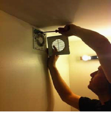
- the fan is fixed at the place of its installation using self-tapping screws of suitable size. In the case when the walls of the toilet are finished with ceramic tiles, a special adhesive is used to fix it, which eliminates the possibility of damage to the tile finish.
Preparation of the switching circuit and supplying electricity

At the next stage of work, it is necessary to supply power to the fan installed and fixed in the niche. For this purpose, first, an electrical wiring diagram is drawn up with the designation of the supply circuits and switching elements, and then the corresponding installation work is performed. In the process of these works, in accordance with the prepared scheme, the route for laying electrical wires is arranged, which are then reliably hidden under a layer of finishing material.
Important! The option of laying wires in the thickness of the walls is used when plaster is used as a finish. To perform these operations correctly, you will have to master the technique of chipping, which consists in preparing small grooves in the walls used for laying the lead wires. Subsequently, such grooves (grooves) are closed with a finishing material or a layer of plaster.
Upon completion of the arrangement of the electrical wiring, the individual cores of the cable are connected according to the schematic diagram (see Fig. No. 4). To connect the cabling, use special terminals located on the fan inlet block.
The figure above shows a variant of the fan commutation line combined with the light switch, which greatly simplifies the installation of the supply circuits.
At the final stage of installation work, a test run of the fan and a check of its operability are carried out.
Specialist recommendations
In the process of carrying out installation work, it is advisable to adhere to the following recommendations:
- In cases where the development of a ventilation system in the toilet is carried out before the start of the construction of a private house, the project should provide a separate power line for the fan with a switch installed in the break in the phase wire of the supply circuit.
- If you do not have the ability or desire to chisel the walls in the bathroom, you can use the option of laying the wires in a special protective casing called a cable duct. The base of such a channel is fixed with an adhesive directly on the walls of the room, and after laying the electrical wiring in it, it is closed from above with a protective cover.
- In the case of using circuits combined with a luminaire to power the fan, the light source must first be disassembled, and then connected to its neutral and phase wires in accordance with the schematic diagram (note that the connection to the phase wire is made at the terminal located after the switch). With the method of connecting the fan we have considered, it will start at the moment the lighting is turned on, and stop working after it is turned off.
- When connecting the fan, it is necessary to strictly observe the basic safety regulations (TB) concerning the rules of handling electricity. In accordance with these provisions, it is possible to start work on the power supply line only after the corresponding consumers are completely de-energized.
- When laying wires openly in a toilet room belonging to a hazardous area (due to high humidity), a special protective device (RCD) must be provided in the supply circuit.