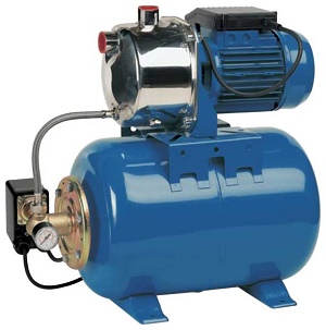
To ensure a stable pressure in the water supply system, a pumping station is used. Its main working units are a pumping unit, a hydraulic accumulator, a relay and an automatic equipment for controlling equipment. Connecting borehole pumps with your own hands can be done according to a one-pipe or two-pipe scheme. The option is chosen depending on the depth of the source.
What type of connection to choose
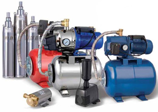
There are two types of pumping stations:
- One-pipe. The simplest, since water is supplied here through a single line, first into the pump housing, then into the accumulator and from it into the main line.
- Two-pipe. The liquid supply is carried out according to a more complex scheme. Water circulates in a circle during the operation of the station. A vacuum is generated, which is created by the impeller of the pressure unit. It is further increased by the inertia of the moving water. Two-pipe surface stations have less power, but they are capable of lifting liquid from a depth of up to 18-20 m.
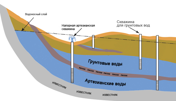
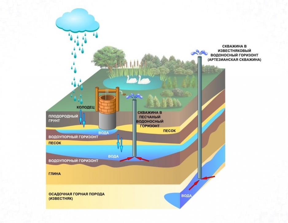
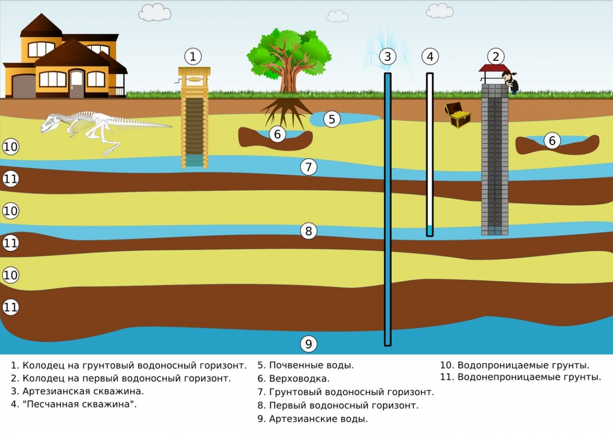
The connection option is selected depending on the depth of the well / well:
- with an indicator of up to 10 meters, a single-pipe connection is optimal;
- at a depth of 10-20, a two-pipe scheme is used;
- if the well has a long length, a submersible deep-well pump is installed.

The type of connection of the station is determined before purchasing the equipment. This allows you to purchase the right amount of consumables.
Stages of connecting a surface and submersible pump
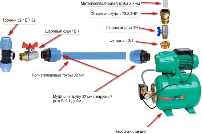
A one-pipe diagram of connecting a pump to a well with your own hands (surface pump) looks like this:
- The unit is installed in a prepared room (caisson, basement). Securely fix it to the base with anchor bolts.
- A water intake hose is connected to the inlet pipe of the pump using a fitting. It is necessary to calculate its length so that the end of the pipe does not reach the bottom of the source for about 1 meter. A coarse filter is put on the end of the hose.
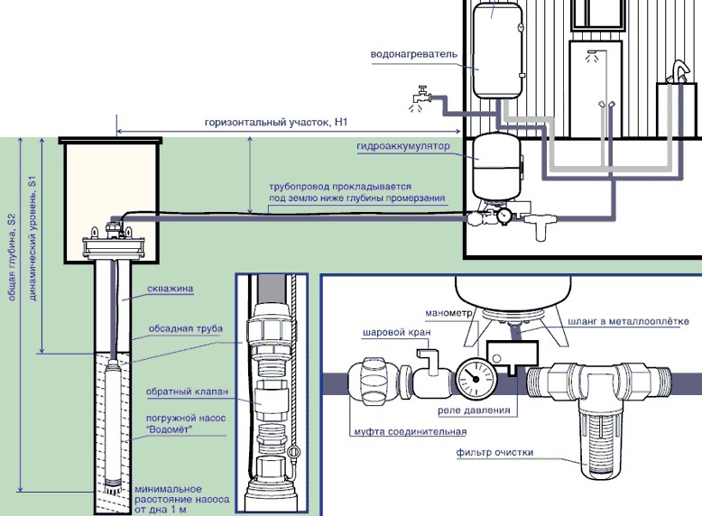
- A hydraulic accumulator is installed and connected with a pipe to a pump. Check valves are installed in front of each entrance to the water intake equipment (for the pump and membrane tank). They prevent backflow of water and incorrect operation of the station.
- The main pipeline is taken from the membrane tank and a check valve is also placed on it a meter from the outlet pipe.
Before starting the system and setting up the automation, water is poured into the technical opening of the membrane tank and pump. Their inclusion dry (idling) is prohibited.
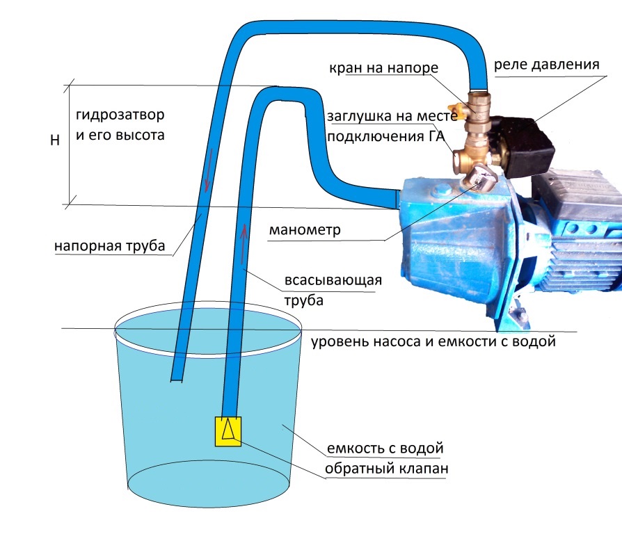
Installation of a two-pipe pump

If the installation of an ejector station is provided, the work is performed as follows:
- Assemble the ejector. A coarse mesh filter is installed in its lower part.
- A plastic bell is attached to the top of the ejector. Later, a squeegee with a diameter of 3.2 cm is fixed to it. It is possible that several fittings will have to be installed in a row until the master reaches the required diameter of the water pipe. The finishing element of the upper structure is a coupling (preferably made of bronze), which provides a transition to the water intake hose. When joining threaded elements, it is better to use seals: rubber gaskets, fum tape, linen winding, etc.).
- An external pipeline is laid and the required hose length is selected, which will later be lowered into the well. Its length is calculated by adding the distances from the point where the ejector is located in the source shaft to the head and from the top of the casing to the pump. The hose is connected to the ejector.
- The intake pipe is lowered to the desired level of the hydraulic structure.
- It remains to connect a pump to it, and then a hydraulic accumulator to the unit.
The station is started after its preliminary filling with water.
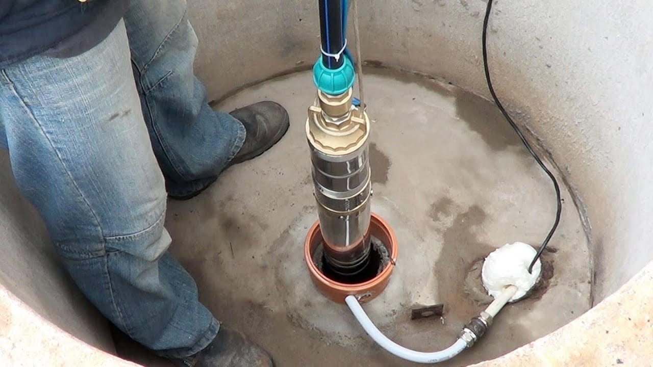
Installation of equipment with a submersible pump
If the well is very deep, the water will have to be pumped with a deep unit. Station setup diagram:
- A water intake hose of the required length is stretched on the surface of the earth. It should correspond to the length of the entire well shaft, taking into account the fact that the pump is located in the source one meter from the bottom.
- With the help of fittings, the pipe is attached to the inlet pipe.
- An electric cable and a safety cable are laid parallel to the hose. To prevent them from twisting and sagging in the well, they are pulled together with construction clamps with a step of 1 m. The ends of the retainers are cut off.
- A membrane tank and a control unit are installed in the caisson or basement.
- The pump is lowered into the well, and the other end of the pipe is connected to a hydraulic accumulator. Be sure to put a check valve on the way.
- The main water supply line is pulled from the accumulator.
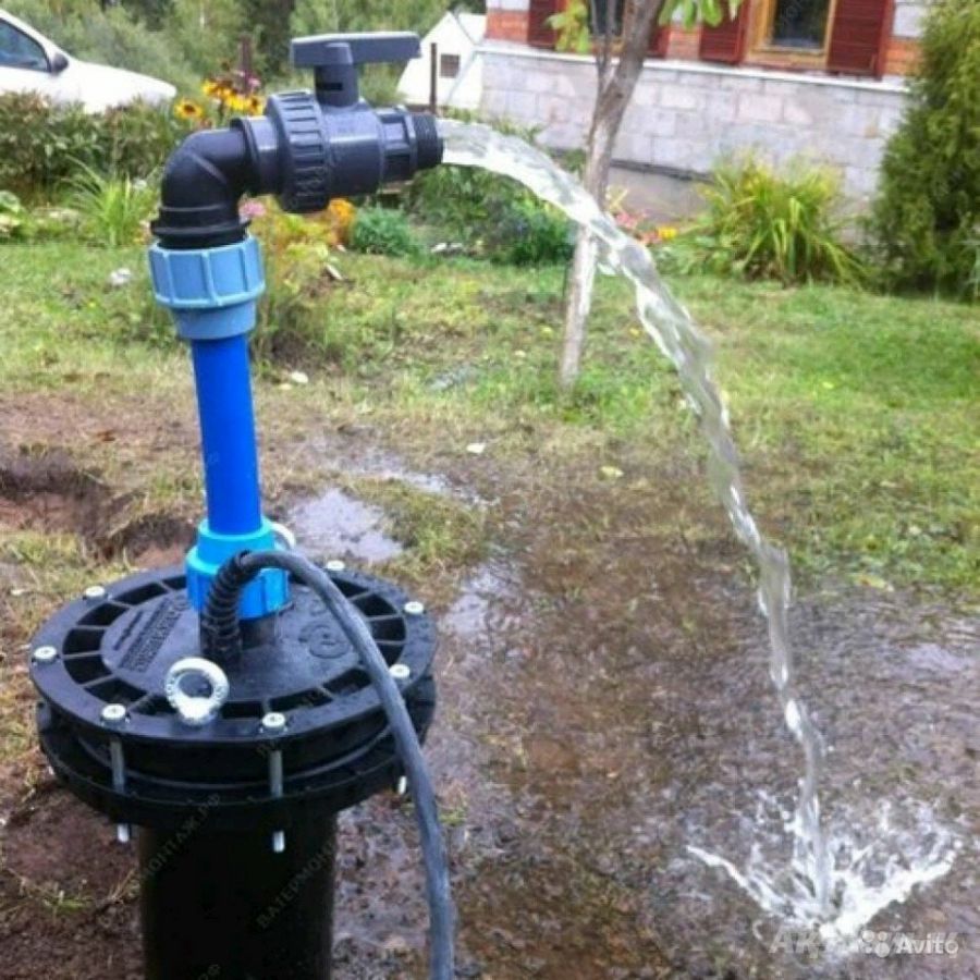
The water supply hose from the well can be led out through an adapter or head.
Connecting the station to the water supply
This technique is more often used in cases where the pressure in the line is too low and it is necessary to stabilize it. The work is done like this:
- At the intended place of the pump station tie-in, the pipe is disconnected. The water is preliminarily drained from the system.
- One end of the line, from which water enters the line, is connected to a membrane tank.
- A pump is connected to the outlet pipe of the accumulator and the second section of the pipe is already brought to it, through which water enters the house.
It remains to bring the electrician and set up the equipment.
Checking pump operation
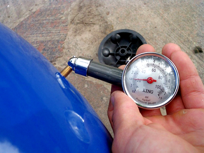
In order for the pumping station to operate in automatic mode with normal on / off cycles, it is important to check the tightness of all connections and adjust the working pressure of the diaphragm tank. Before starting the equipment, the cavities of the pump and accumulator must be filled with water.
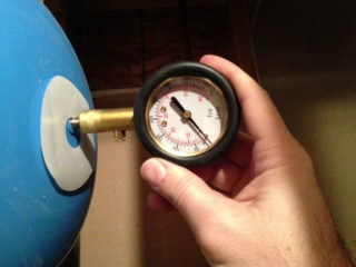
After the start of the work of the station, they monitor at what pressure indicators the equipment is turned on and off. The optimum low for inclusion is considered to be 1.5-1.8 bar. A good overhead for shutdown is 3-3.5 bar. If the wizard notes a discrepancy between the actual indicators, you need to adjust them. To do this, open the cover of the relay and turn the screw marked "DR" (indicator for shutdown) towards + or -. These symbols indicate an increase or decrease in atmospheres, respectively. The switch-on pressure is adjusted using the screw marked with the letter "P".
A correctly assembled and connected station works cyclically and does not show any leaks. If the master did everything correctly, you can backfill the external water supply system. It is advisable not to tamp the soil. It is gradually poured in after the drawdown.