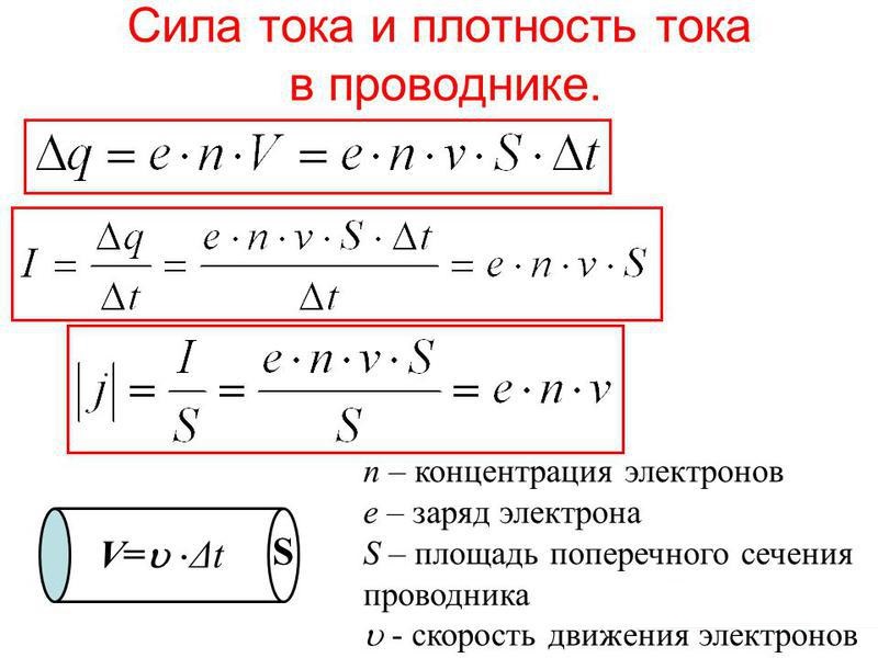
In general terms, the amperage (CT) is a value that shows how much electricity has passed through the cross section of a conductor in one second. In this case, it is believed that in a conductor it reaches a value of 1 A in the case when an amount of electricity equal to 1 coulomb passes through its cross section every second. Measure it in amperes (A). Additional units such as milliamperes (1/1000 A) and microamperes (1/1000000 A) are also used.
Why you need to measure current
- I = U / R
- U = I * R
- R = U / I
At the same time, it is simplified to assume that a current of 1 A arises in a conductor with a resistance of 1 Ohm if a voltage of 1 V is applied to it.
Having measured the CT with a multimeter, you can:
- to clarify the real power consumption of a particular electrical appliance;
- find defects in the electrical appliance if its real power does not correspond to the value declared in the documentation;
- find out the electrical capacity of autonomous power sources (batteries, etc.);
- identify the existence of a current leak in electrical circuits and, if necessary, localize the defective area;
- check the battery charger to see if the charging current matches the specified value, etc.
Such measurements are carried out using special devices - ammeters. There are enough varieties of them on the domestic market to satisfy the needs of all buyers.
The most popular, especially at the household level, are small multifunctional (ammeter + ohmmeter + voltmeter) multimeters, with which you can measure almost all the necessary parameters of the electrical circuit.
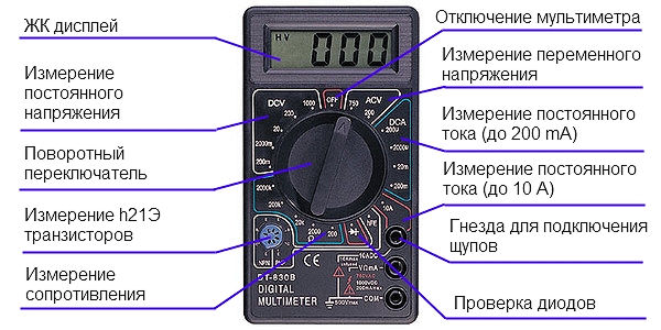
Multimeter device
A modern multimeter (tester) is a complex electronic device. These measuring devices differ in the principle of operation and the way in which the results obtained are displayed. At the same time, their structure and appearance entirely depend on the manufacturer, who has the ability to equip the multimeters with additional capabilities. For example, there are testers equipped with built-in conductive clamps that allow you to measure the electrical parameters of circuits without breaking the wires.
Classification and principle of operation
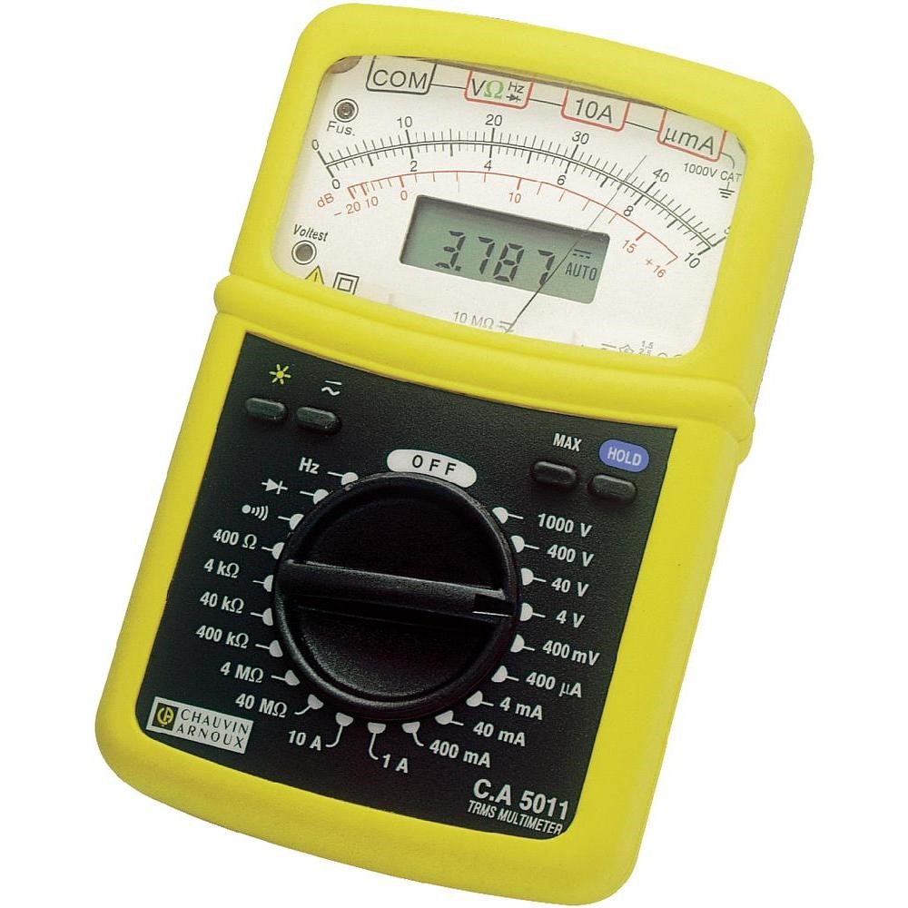
By design, multimeters can be stationary and small. In addition, based on the schematic solution, they can be:
- analog;
- digital.
Stationary multimeters work, as a rule, from a centralized power supply network. They are high-precision electronic devices and are used for precision measurements in laboratory or production environments. They also work as part of information and measurement systems and specialized industrial complexes.Small-sized (pocket) testers use built-in batteries or replaceable power supply elements to measure resistance.
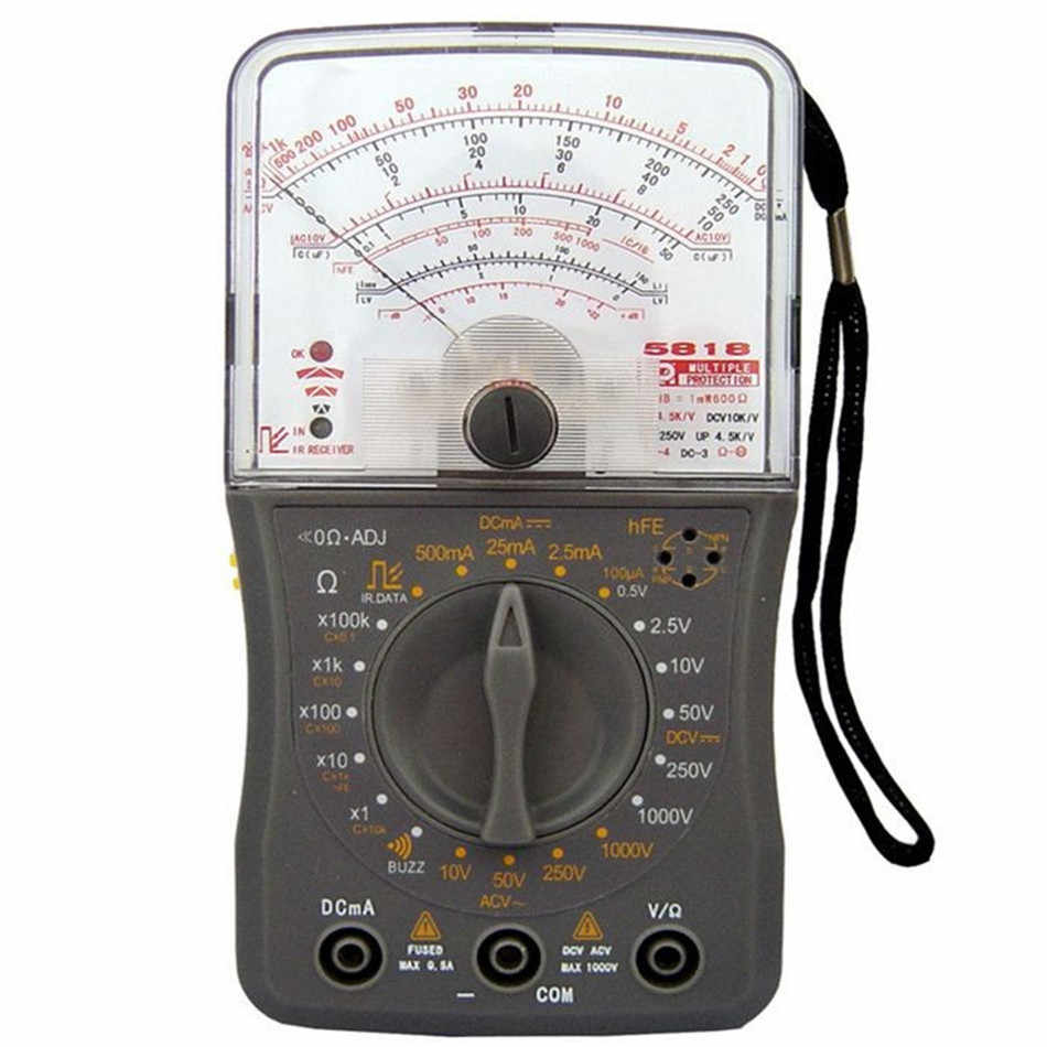
In analog multimeters, the measurement result is displayed by the deflection of the arrow on a graduated scale, and in digital - on an LED display or LCD screen. There may also be original models equipped with a pointer indicator and a digital screen at the same time.
The electrical circuit of analog type dial-up multimeters is simple and consists of a set of shunt precision resistors of large and small rating. In order to use such testers to measure the parameters of AC electrical circuits, rectifier diodes are introduced into the circuit. This is due to the fact that the magnetoelectric system of the pointer microammeter operates only on direct current.
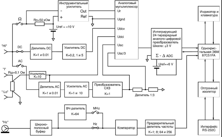
The electrical circuits of digital multimeters are much more complicated and contain the following units:
- operational amplifier;
- attenuator;
- analog-to-digital converter;
- high-precision rectifier;
- mechanical or electronic switch.
The block diagram is the basis for all digital multimeters and allows you to measure the parameters of AC and DC electrical circuits with high accuracy.
The principle of operation of analog testers is based on the fact that the measurement is preceded by the conversion of all incoming signals into amperage, which is then measured. In contrast, digital multimeters pre-convert all incoming signals into voltage.
Basic principles of current measurement
The main condition that must be met when measuring CT in an electrical circuit is to turn on the tester in the wire break of this circuit, that is, to become its component for the time of measurement. Before measuring the current strength with a multimeter, it is equally important to correctly set on the device:
- measurement mode (direct or alternating current);
- upper limit of measurements.
Incorrectly set parameters will necessarily lead to a breakdown of the measuring device.
When the user does not know the order of magnitude of the current in the circuit, it is necessary to set the maximum measurement limit. If the set range turns out to be overestimated, it is gradually reduced using the tester's operating mode switch.
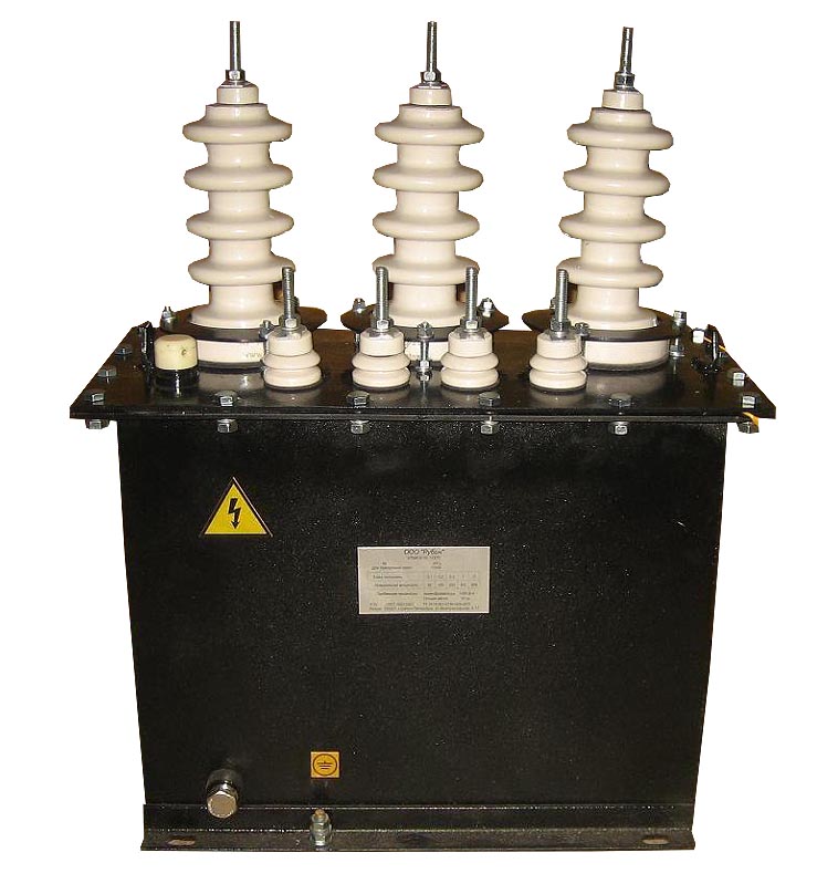
The device for measuring the current strength is connected to the electrical circuit in series with the load. When measuring high currents, the multimeter is connected to the circuit through a current transformer, shunt or magnetic amplifier. If measurements are to be taken in electrical circuits with a voltage of more than 1 kV, use a current transformer (alternating current) or a magnetic amplifier (direct current).
Safety engineering
Measurements carried out in electrical circuits under dangerous voltage ~ 220 V require compliance with safety regulations. A current of no more than 0.001 A is considered safe for humans. Any, even a slight excess can lead to injury to the user. Therefore, when working with electricity, you need to be extremely careful and take special care.
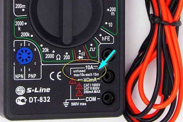
When working at the upper limits of the multimeter, measurements should be taken as quickly as possible. This is due to the fact that many testers do not have overheating protection, and with prolonged contact with high current they can simply burn out, which in turn is fraught with electrical injury. Sometimes manufacturers of multimeters warn users about such a danger, stipulating, for example, that the permissible measurement time should not exceed 10 seconds. no more than once within 15 minutes.
The connection and disconnection of the multimeter is carried out after the electrical circuit is completely de-energized. They supply power and start measurements only after all work on connecting the tester is completed.
To avoid electric shock, you must take measures to prevent touching exposed live parts. It must also be remembered that when a functioning electrical circuit is opened, an electric arc may occur, which will also provoke an electrical injury.
Current measurement
At home, the current strength in electrical circuits is measured in cases where it is necessary, for example, to determine the real value of the power consumption of an electrical appliance or to compare the technical parameters of an electrical appliance connected to the network with the real possibilities of electrical wiring. In this case, it is necessary to remember about the dangers that await the inexperienced owner of the multimeter when trying to make such measurements in an electrical outlet. As a rule, this leads to complete failure of the tester, and in some cases - to electric shock to the user.
There is no current in the power outlet. On its contacts there is only voltage between phase and "zero". The current in the mains appears only after the electrical appliance is connected to the outlet.
If you insert the probes of a multimeter that is in the current measurement mode into the holes of the socket, a short circuit will occur in the network and the measuring device will fail. It is good if it is equipped with a fusible link that will simply burn out and disconnect the tester from the network. If such a fuse is not provided by the design of the device, the multimeter may ignite or even "explode" due to overheating.
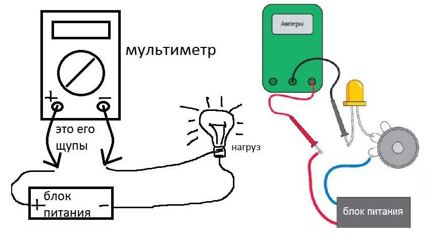
Measurement of CT in the circuit of an electrical appliance connected to a power source
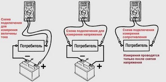
To measure the current in the circuit of the connected electrical appliance, the multimeter must be connected to the break of one of the power wires, as shown in the diagram.
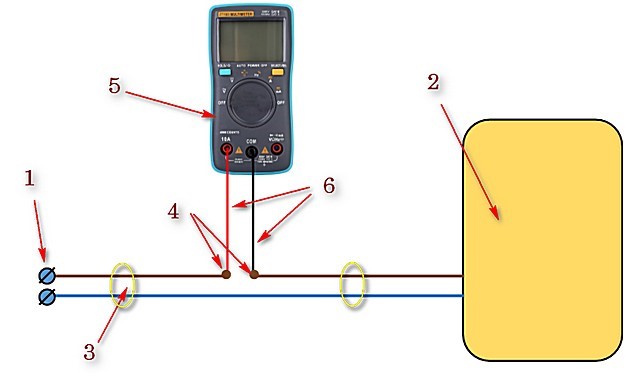
Here:
- 1 - AC outlet or contacts of an autonomous power supply;
- 2 - electrical appliance;
- 3 - wires (cable) power supply of the electrical appliance;
- 4 - the place of the electrical circuit break and the connection of the multimeter probes;
- 5 - tester included in the alternating current measurement mode;
- 6 - test leads supplied with the multimeter.
To connect a multimeter to a break in an electrical circuit, it is necessary to cut one of its conductors and strip the insulation at the cut ends.
The current is measured in the following sequence:
- The required measurement mode is set with the knob of the multimeter switch, taking into account the type of current (alternating or direct).
- The same handle is used to set the upper limit of the CT measurement. In this case, it is recommended to initially select a measurement limit that exceeds the expected value of the measured parameter.
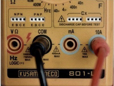
- Insert the test leads into the corresponding sockets on the multimeter.
- Connect the tester probes to the stripped ends of the wire and make sure the contact is secure.
- Switch on the power supply of the device and record the readings of the multimeter. If necessary, you can change the upper limit of measurements and re-record the result.
- Turn off the power supply and disconnect the tester probes from the ends of the conductor.
- Connect the cut wire and insulate the area carefully.
When making measurements in DC circuits, it is necessary to observe the polarity of the connection of the test leads.

If you need to measure the current without violating the integrity of the electrical circuit, the best option would be to use a multimeter equipped with a built-in clamp meter.
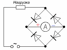
Sometimes the need to measure the current in the AC circuit may arise at a time when there is no multimeter with such a function at hand. However, radio amateurs found a way out of the situation by using testers operating only on direct current to measure the current in AC circuits.It is enough to supplement the electrical circuit with a diode bridge by turning on a multimeter that measures the parameters of DC circuits according to the following scheme:
A similar result can be obtained if a special calibrated shunt with a known resistance is included in the circuit. In this case, the shunt is selected in such a way that its rated voltage coincides with the rated voltage of the measuring device.
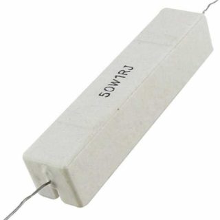
Then, parallel to the shunt contacts, connect a multimeter with the set voltage measurement mode (voltmeter) and measure the voltage drop across the shunted section of the power network. How to measure the voltage with a multimeter is indicated in its instruction manual.
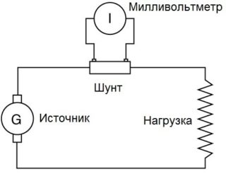
In this case, the multimeter acts as a voltmeter, but the magnitude of the measured voltage will be directly proportional to the current strength. Knowing the resistance of a precision shunt, using the formula I = U / R, you can easily calculate the value of the current in the circuit. If you take a calibrated shunt with a resistance of 1 ohm, its nominal value can be determined on the voltmeter scale (I = U / 1 = U).
At home, such a low-resistance shunt (R = 1 Ohm) is easiest to make on your own, for example, by winding a small piece of thin nichrome wire (section - 0.123 mm, resistivity - 7.94 Ohm / m, diameter - 0.4 mm) 126 mm, on a fiberglass bar.
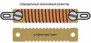
By installing a homemade resistor in the open circuit and connecting a multimeter to its contacts, you can measure the voltage on the shunted section of the circuit. Its value at face value will correspond to the current flowing through the resistor: I = U / 1 = U.


Pleasantly surprised. Like for correct and competent presentation. I would like to add that the instructions for the DT 83x series multimeters indicate that during current measurement / does not apply to the 10 A limit / switching limits is inadmissible / the switch contacts may be damaged /.