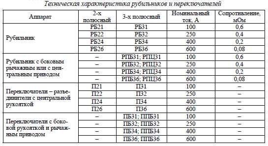
Rocker-type switches are manually operated devices that make several commutations with one movement. They are used in switchgear systems to close and open an electrical circuit. The rocker switch is designed for amperage 100-1000 A and voltage up to 400 V, suitable for residential and industrial premises.
- What is Rocker Switch
- Specificity of the device
- Pros and cons of using circuit breakers
- Switch types
- Single pole circuit breakers
- Two-pole versions
- Double capacitor switches
- Changeover switches
- Areas of use
- Features of the three-position switch application
- Installation of devices
- Inclusion order
- Basic connection diagrams
- Single-phase network
- Two-phase line
- Three-phase power grid
- Connecting a generator to a changeover switch
- Self-assembly of a toggle switch for a generator
- Practical recommendations for operation
What is Rocker Switch
The purpose of the toggle switch is to transfer voltage between two lines or connect several networks. Using a circuit breaker, you can eliminate current leakage in case of accidents and quickly switch to the whole line. Switching of the device is carried out using the lever on the front panel, which is set to 1-2 positions
The equipment is installed in the switchboard room or near the input panel.
Specificity of the device
The rocker switch is similar to the two-position switch in principle of operation, but differs in increased power and smooth knife drive. The second difference is the process of switching with a break in the line and working in three positions:
- apartment / home network;
- shutdown;
- power supply from the generator.
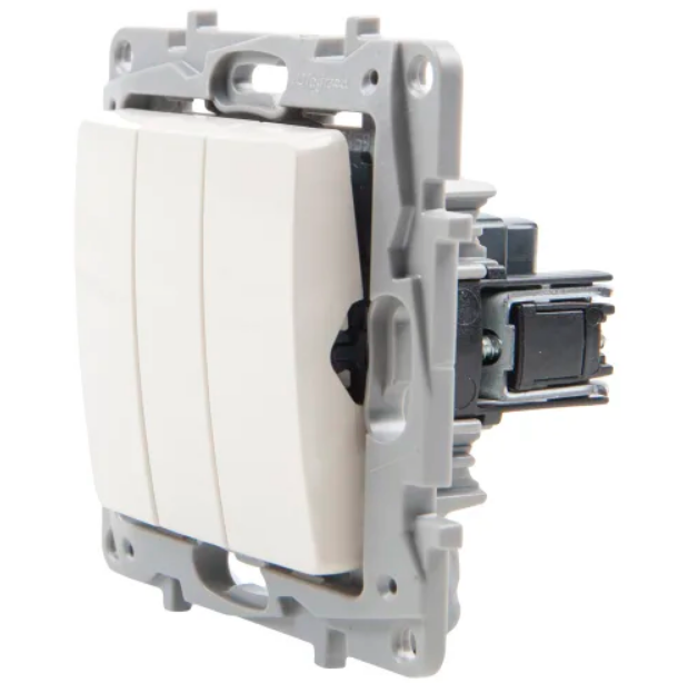
To understand the principle of operation of the rocker switch, you need to understand the design. The middle contact is a strip in the middle with V-shaped knives. The upper and lower terminals are used as lateral ones. The middle contact connects only to the top or only to the bottom. The knives do not have accelerators or springs, so the transfer from the main to the backup network is done manually.
Pros and cons of using circuit breakers
An electric breaker is the simplest device with advantages and disadvantages. The advantages of operation include:
- Visibility. The device can be visually inspected for damage. The position of the knives is clearly visible.
- Simple constructive. A small number of components simplifies maintenance and repair of the device.
- High switching current. The switch switches a current of 500, 630 or 1000 Amperes.
- Low cost. You can buy a switch for installation in a private house or apartment.
Despite the positive characteristics, the machine has several disadvantages:
- Open type of construction. All elements are in plain sight, with careless touch there are risks of electric shock.
- Irregular switching speed. If the knives are moved slowly, a high-temperature arc is formed, which burns out the internal parts of the appliance.
- Possibility of short-circuiting in the event of a high-temperature arc.
- The occurrence of inrush currents during switching before the load is switched off.
To protect the exposed parts, the toggle relay is hidden in a special box.
Switch types
Connecting devices according to different schemes and differences in operating parameters imply the division of switches into types.
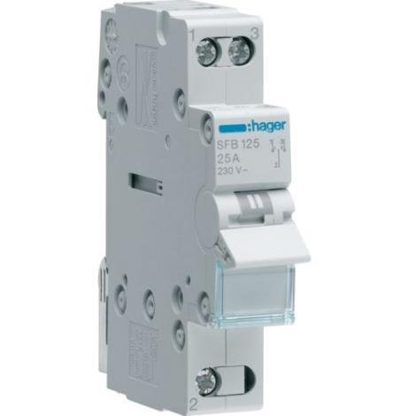
Single pole circuit breakers
The devices have one module and copper conductors. Differs in low, about 200 V, output voltage. The main application of the changeover circuit breaker is for the maintenance of a generator with an operating frequency of up to 20 Hz.
The modular device is not installed in a residential building that consumes a lot of energy. The maximum load of the apparatus should not exceed 200 A.
Two-pole versions
The purpose of the changeover switches in two directions is the maintenance of high-rise buildings, equipment connected to a two-phase or single-phase network. The device has an average negative resistance rating of 60 ohms. The type of output voltage depends on the modification of the switch.
The switch is suitable for connection to a two-phase network. Equipped with blockers, has a high sensitivity limit. Available with two or three modules. For generators, models with a voltage of 350 V, designed for a load of 30 A.
Popular two-pole networks are PP20 with open-type capacitors, which require a 300 V power supply.
Double capacitor switches
The toggle switch is designed for single phase circuit only. The devices are produced with two capacitors and two modules, work in conjunction with power supplies for 300 V. The average voltage is 30 A.
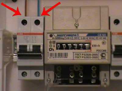
The devices are installed with two copper jumpers. Two-capacitor models are only compatible with expansion switches.
Devices can be combined with counters.
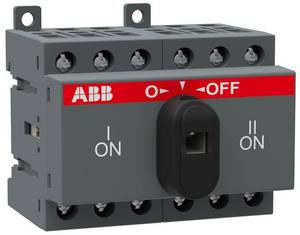
Changeover switches
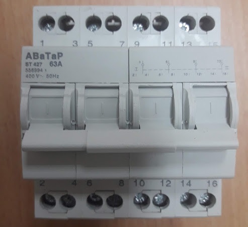
The electric breaker provides disconnection of the network from one energy source and connection to another. The presence of the midpoint explains the name “crossover”. The devices are manufactured with arcing arresters providing switching when the voltage is connected. Models without arcing mechanisms are switched when the load is switched off. The circuit breaker works only in manual mode - switching is carried out using an isolated control lever.
The design of the device is presented:
- sealed body;
- movable knife contacts with two working positions and one intermediate;
- an arc chute, but there are circuit breakers without it;
- terminals for connection to the network.
Connection to one load line is carried out according to the principle:
- The main power supply is connected to contact No. 1.
- A diesel or electric generator is connected to contact No. 2.
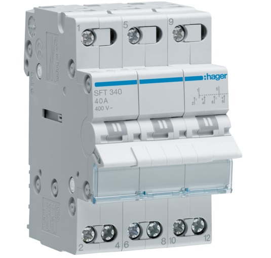
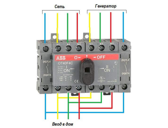
If you need to enter a building with a three-phase voltage, a three-phase switch with 4 poles is used. The device is connected like this:
- You need to enter the mains through 4 terminals.
- The generator is thrown on 4 terminals.
- The load is connected to 4 terminals.
Zero is connected to one terminal out of four, phase is connected to three.
Areas of use
The main purpose of the devices is to transfer the load between two or more sources. They are used to:
- switching the backup power supply;
- transfer of the load from the main equipment to the backup;
- switching from one source to the second without the presence of a load.
The switching speed of the breaker should not depend on the operator - this will prevent burnout of the contacts.
Features of the three-position switch application
A three-pole isolator is suitable for connecting a back-up power supply to the home line. It is used only after disconnecting the load. The generator will need to be activated and put into working position. Then you need to connect the house network to it. When carrying out repair work, the switch will be used as a disconnector.
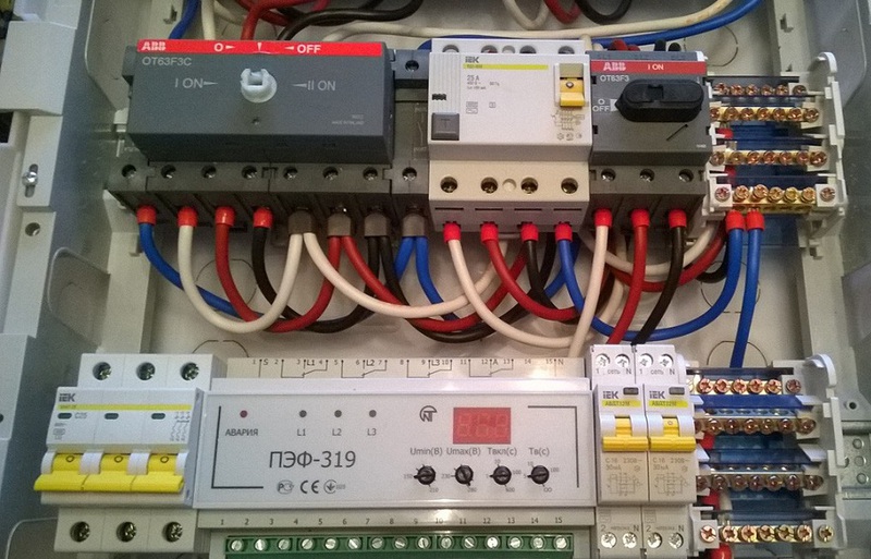
Installation of devices
Changeover electrical equipment is installed in the switchboard. For indoor installation, models with a plastic housing are suitable, for outdoor installation - a metal one.Inside the boxes there is a special DIN rail for circuit breakers. Installation of devices is carried out as follows:
- Load cut-out models are installed vertically.
- The type of tires and wires is selected. Their cross-section must correspond to the current rating of the switches.
- Busbars and wires are connected to fixed contacts.
- The elements are tightly clamped with terminals for reliable contacts and eliminating the possibility of overheating.
- The threads of the nuts are covered with petroleum jelly.
- Contact nuts tighten smoothly. After the first turn of the wrench, the nut is loosened and then carefully tightened.
- Castor oil is applied to the surface of the contact knives, which will prevent them from jamming in the racks.
- Grounding of metal non-current-carrying elements is made on the outer part of the box.
In order for the switch to work without interruptions, the installation is carried out indoors. The device needs to be protected from moisture, and then check the firmness of the fit on the DIN rail.
Inclusion order
Three-position, or packaged devices are produced without a disconnector. They connect like this:
- Stopping the introductory machine.
- Installing the handle of the device on the generator line.
- Switching off the load breaker.
- Connect the switch cable to the generator outlet.
- Starting the generator, waiting for warm-up (2 minutes).
- Power supply to the switch.
- Switching on automatic machines.
Automatic machines are placed on each of the inputs.
Basic connection diagrams
The toggle switch connection diagram is determined by the type of power supply.
Single-phase network
Only two-pole versions with power supplies with an operating voltage of 300 V are connected to this line. Connection is made with a negative resistance of 50 Ohm. Devices are placed on copper jumpers. Installation in a residential building is carried out in switchboards of the KK220 type.
Reversible units for a single-phase network are not suitable.
Two-phase line
For a two-phase network, only expansion switches are suitable. You will need to add a connecting node to them - power supplies for 220 V. The maximum voltage of modular devices is 300 V, but the presence of two modules allows a voltage limit at the output of 350 V.
The process of connecting switches has several nuances:
- the blocker is installed in the electrical panel together with the thyristor unit;
- negative resistance rating is 40 ohms;
- contact systems are used only in closed circuit breakers;
- if you have two reversing units from different manufacturers, you will need a controller.
The controller is used to prevent network harmonic distortion.
Three-phase power grid
The switch is combined with a power supply with a rated operating voltage of 400 V, pulse transformers. You can enter the device through the inverting output. The output currents will be fed through the feed-through capacitors.
For a three-phase network, it is allowed to use two-module and single-module devices. The latter must have a threshold voltage of 350 V and a negative resistance of 55 ohms.
For three phases, only a switch with a blocker is suitable.
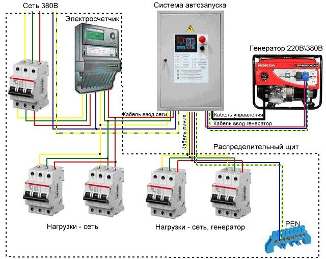
Connecting a generator to a changeover switch
To organize the coupling, you will need two modular contacts or an electrical changeover for 7 contacts. A pair of them should be normally closed, and a pair should be normally open. The connection is carried out as follows:
- It is required to enter the extreme contact of the switch on the line and cable entry of the station.
- The middle contact is connected to the consumer.
- The switch is put in its original position - connecting to the main network.
- During the transfer, power is supplied from the generator.
- The switch is installed in the control panel.
- To warm up the system and supply power after activating the generator, a time relay is installed.
- The backup contactor is powered through the main bushing communicator via a normally closed contact.
Switching processes are implemented by the user. He sets the switch to neutral in the event of a voltage drop. When it resumes, the first contact is activated, opening the power circuit of the second input.
Self-assembly of a toggle switch for a generator
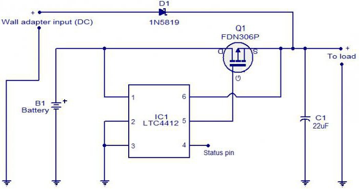
Making a switch with your own hands is done step by step:
- Selection of machines by the number of switching circuits. On the two-phase, 2 two-pole or 4 single-pole models are installed.
- Installation of automatic machines in the shield. One is placed in a standard position, the second is turned over.
- Switching nodes with wires.
- Installing a steel retainer in the pusher (there are gaps for it in the machine). The bar will allow you to switch all machines at the same time.
- Checking the quality of the system - you should hear a click.
You cannot make a three-position switch on your own - you only get a two-position device.
Practical recommendations for operation
- The device is operated at temperatures from -40 to +50 degrees.
- The reversing switch is only installed in the enclosure with the mounting plate.
- It is allowed to manually activate circuit breakers with arcing and breaking contacts.
- The burnt contact knife is cleaned with a file or glass paper.
- Tighten the fixing bolts to prevent the legs from skewing.
- All active parts of the device are isolated.
- For manual phase transfer, a two-way transition switch is suitable.
- You need to choose a switch according to the power of the transmitted current.
If there is no voltage in the main network, the generator is first started, and then the switch is switched to the operating position.
Changeover switches are suitable for installation in apartment buildings, in production with backup generators. Devices simplify maintenance of power supplies, monitor power lines and protect equipment connected to it.