Users of 380 volt power circuits in the household need a passive (uncontrolled) three-phase rectifier. Knowing some of the features of an electronic device and existing rectification circuits will prove to be very helpful. This will help the owner of the power equipment to operate it more competently and efficiently for a long time.
Rectifier Description
The main difference between the devices and their single-phase counterparts is as follows:
- the first ones are installed in 220 Volt lines and serve to obtain constant currents of small magnitude (up to 50 Amperes);
- three-phase rectifiers are used in circuits where the working (rectified) currents significantly exceed this indicator and reach several hundred Amperes.
- in comparison with single-phase samples, these devices have a more complex structure.
Known rectification circuits of three-phase voltage, allowing to obtain the minimum level of ripple at the output.
In electrical engineering, they are called "three-phase bridge rectifiers", because by the way they open the diodes, controlled by voltage polarity, they resemble a one-way bridge over a river. Only the direction of the flow of electrons in them alternates with a frequency of 50 Hz, which is inaccessible for cars to pass alternately to each side.
Operating principle
The principle of operation of any sinusoidal voltage converter is based on the rectifier properties of a special semiconductor element - a germanium or silicon diode. When an alternating current flows through it, the positive half-wave freely "passes" through the working electronic junction, shifted in the forward direction. When exposed to a negative half-wave, electrons encounter an obstacle in the form of a potential barrier, so that current cannot flow through the junction.
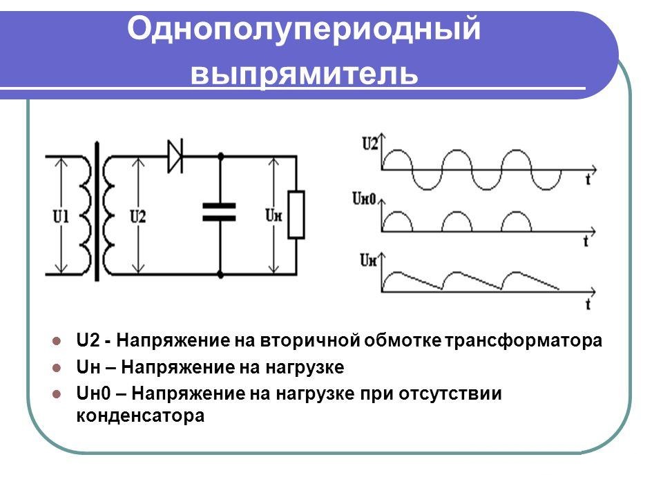
In the simplest switching circuits, an incomplete cycle of processing of variable levels is used, since the second half-wave is irretrievably lost. This significantly reduces the convertible power. To preserve the useful component, 2-full-wave rectification circuits were developed, in which the number of diodes was increased to two.
A "full cycle circuit" can contain 4 rectifier elements, but this is a bridge circuit.
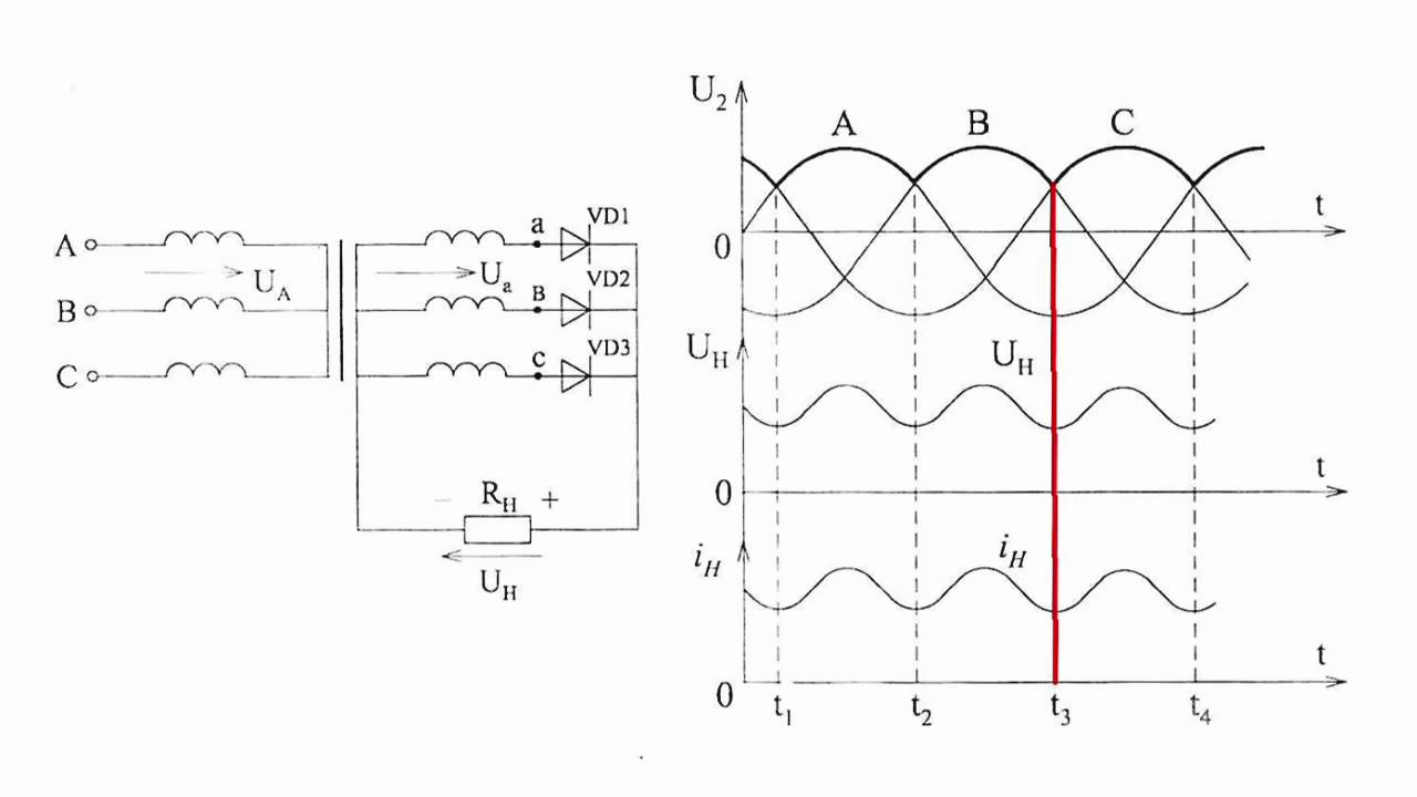
Half-wave multiphase rectifier
In total, a half-wave rectifier sample uses three semiconductor diodes with loads connected to them. After studying the diagrams of voltages and currents obtained at the output of the electrical circuit, the following conclusions can be drawn:
- the efficiency (efficiency) of such a device is very low;
- useful power is lost when processing negative half-waves of all three phases;
- when using such devices, it is very difficult to obtain the required load characteristics.
All these disadvantages of half-wave circuits forced the developers to complicate them by applying the principle of double parallel conversion.
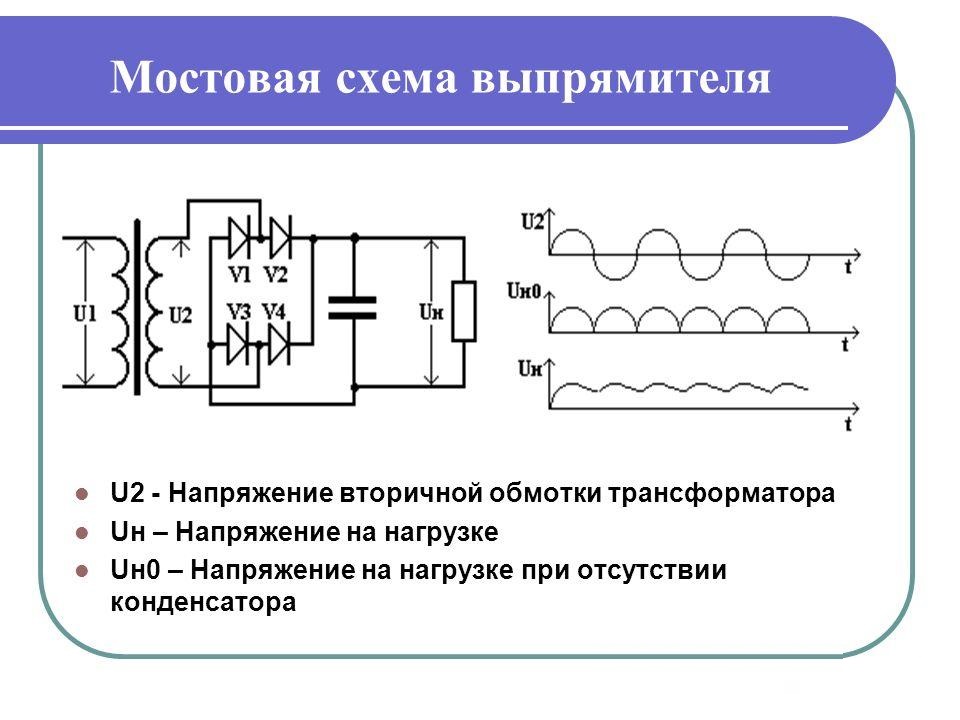
Full-wave rectifier
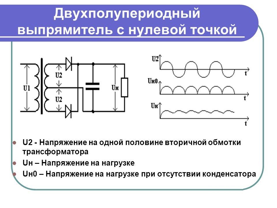
The classical connection in this case is made according to the Larionov scheme, after which the rectifier itself is named.
An analysis of the operating diagrams of such a rectifier clearly demonstrates its indisputable advantages. During the operation of these circuits, both positive and negative half-waves are used, which raises the efficiency of the entire converter. This is explained by the fact that the three-phase structure of the circuit, together with full-wave rectification, provides a sixfold increase in the ripple frequency. Due to this, the signal amplitude at the output after the smoothing capacitors increases significantly (in comparison with a half-wave rectifier), and the power supplied to the load increases.
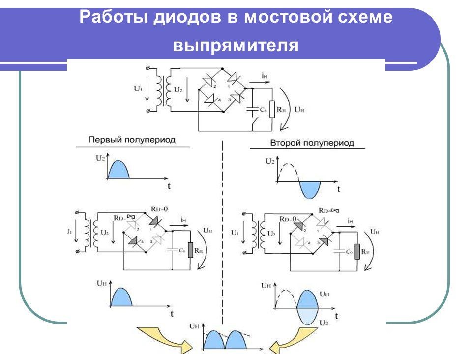
Bridge devices
The principle of operation of a three-phase bridge rectifier is easiest to imagine as follows:
- when an alternating potential acts at its input, for each half-wave, two out of four diodes turn out to be open, connected as if in a mirror;
- in the first case, the positive half-wave of the input voltage is rectified, and in the second, the negative one;
- As a result, at the output of such a cross-circuit, a plus always acts on one pole of the bridge, and a minus on the other.
Both in three-phase rectifier bridges and in full-wave circuits on diode junctions, part of the input voltage is lost (on each diode - no more than 0.6 Volts).
The total loss per cycle (positive and negative) in a three-phase bridge will thus be 1.2 Volts. Rectifier equipment designers always take into account these losses and pre-set slightly overestimated input parameters to obtain the required output power.
Bridge voltage diagrams or plots are the best confirmation that this way of connecting diodes to the rectifier circuit provides maximum energy transfer. At the same time, small voltage losses at the junctions can most often be compensated for due to better filtering in the secondary circuits.
Features of a three-phase bridge and options for its construction
The more phases (or pairs of diodes) are used in the rectifier circuit, the lower the output voltage ripple.
As an example, consider a device with 12 rectifier diodes. One of the groups in the amount of 6 pieces is included in this case according to the "star" scheme with a common zero point, and the second - into a triangle (without ground). Taking into account the fact that the rectifiers are connected in series, the potentials at the output of the system are summed up, and the ripple frequency in the load turns out to be 12 times higher than the mains value (50 Hertz). After filtering, the voltage supplied to the consumer is characterized by a higher quality.
Comparison of single-phase and three-phase devices
- the first are used only in 380 Volt power networks, and the second type is allowed to be installed in both single-phase and three-phase circuits (one for each of the phases);
- rectifiers 380 Volt allow you to convert large power and develop significant currents in the load;
- on the other hand, making a three-phase rectifier on your own is somewhat more difficult, since it consists of a larger number of components.
The calculation of a three-phase rectifier will also be more difficult, since in this case the vector components of the effective currents and voltages are taken into account. This is due to the fact that in 380 Volt circuits the phase parameters are shifted relative to each other by 120 degrees.
It is not difficult to understand the essence of the operation of a three-phase rectifier. To do this, you will need to familiarize yourself with the basics of valve devices and analyze the electrical circuit for their connection. Knowledge of the principle of operation of rectifiers will help the user to use it more efficiently in everyday work.


Guys! Have you heard anything about Larionov's scheme? Only 6 diodes and no problem.