The concept of "current relay" is widespread in electrical engineering, and this unit itself is an obligatory component of most protective devices: circuit breakers, disconnecting devices and the like. It is important to know and understand the design features and the principle of operation of such relays not only for a beginner, but also for an experienced specialist. But first of all, you need to understand the device of this switching element, as well as with all the variety of its types and types.
Current relay device
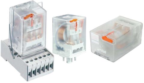
It is most convenient to get acquainted with the design features and the principle of operation of a current relay (TR) on its most common type - an electromagnetic device.
Unlike induction and electronic analogs, the device of an e / m protective device allows you to visualize how it works.
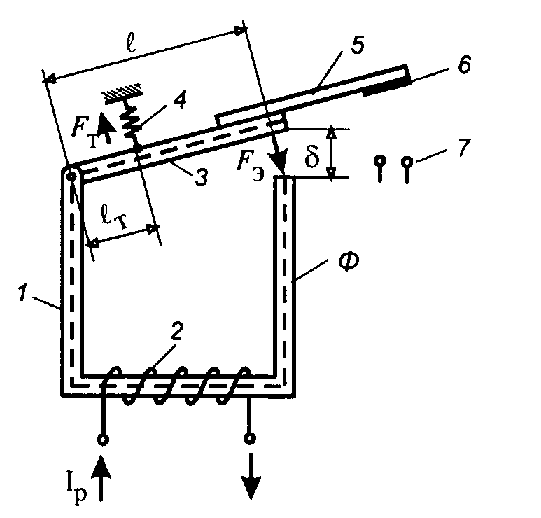
Any solid-state current relay contains the following mandatory elements:
- Magnetic circuit (core), consisting of 2 parts and having a constant or adjustable air gap.
- Bobbin with a coil located on the fixed part of the core.
- A spring located on its movable half and creating a counter moment when the relay is triggered.
In addition to the listed nodes, it includes auxiliary elements that increase the functionality of the system.
Operating principle
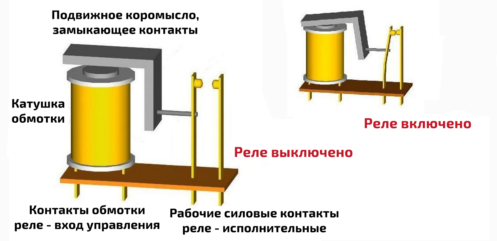
The electromagnetic device is triggered by an e / m connection created by the flow of alternating current through the coil and causing the attraction of both halves of the core. This action, which is simple at first glance, contains some nuances:
- the spring on the movable part counteracts the approach of its two halves;
- it is possible to overcome its resistance only at a certain current strength in the coil;
- this value is the main indicator characterizing the operation of the current relay.
When a current appears in the coil, an EMF is induced in the core, due to which the halves are attracted, but not completely - the spring prevents them from doing this. When it reaches a certain value, the EMF becomes so large that it overcomes its resistance.
To return the system to its original position, the current in the relay will need to be reduced to a certain value, depending on the return coefficient. This indicator is associated with the design features of the relay of currents and voltages and is configured for each of them individually. To do this, it is enough to adjust the spring tension, which you can do yourself.
Purpose and connection methods
TP is the main component of all protective devices installed in power circuits. Based on this, the features of the use of the device should be considered.
Its main purpose is to serve as an executive element in the composition of circuit breakers, residual current devices and many similar devices. In accordance with this, the scope of their application is determined in conjunction with the devices indicated above.
- Power circuits of high-voltage lines and the protective equipment available in their composition.
- Switching distribution boards, into which TP are included separately or as part of other devices.
- Household single-phase inputs and distribution (linear) devices installed within household shields.
In accordance with the purpose of the switching devices, their switching circuits are selected.
Several methods can be used to connect the relay machine to existing power grids or other circuits. They differ in the type of protected equipment:
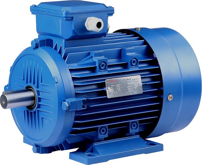
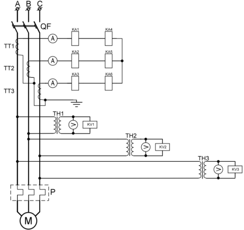
- three-phase asynchronous motors;
- consumers connected to 380 Volt power networks;
- loads connected at the output of circuits with a supply voltage of 220 volts.
In accordance with the first of these paragraphs, TR are used as e / m releases that turn off the circuit when the operating currents exceed the permissible level. When installed in three-phase circuits, they perform the same function, but with a wider range of functionality. As releases, they are part of powerful contactor devices and e / m starters.
Relays installed in input (linear) machines and RCDs have a slightly different purpose. Here they perform the function of sensing elements providing current cutoff (setpoint) operation. When switched on, they are set to such limiting operating modes as overcurrent, short circuit and leakage.
According to the terminology accepted in electrical engineering, in the first two cases, they are logically positioned as overcurrent relays.
In the protective circuits of electric motors, along with disconnecting relays, bistable thermal elements on bipolar springs are installed. They provide some delay, which allows not to remove the power supply from the windings in starting modes.
Types of TR
All known samples of current relays are classified according to the following criteria:
- by the method of installation (connection diagram);
- for its intended purpose;
- by execution (modification).
In accordance with the first of these features, the existing TR models are divided into direct mounting devices and indirect switching devices (through current transformers). By design, they are subdivided into built-in devices and designed as a separate module to be installed on a DYN-rail.
According to their intended purpose, they are produced in the form of products used for the following purposes:
- protection against single-phase short circuits;
- limitation of negative sequence currents;
- as differential protection;
- in the form of remotely controlled independent modules.
For direct and indirect inclusion
Devices intended for direct connection, according to the instructions for use, are installed in a network with an effective voltage of up to 1000 Volts and a limited current value. With its significant amplitude, inclusion in a circuit break is unacceptable, since the relay is not designed for power modes of operation. In this case, a current transformer is required, which makes it possible to reduce the value of the controlled value several times. In three-phase networks, such relays are installed in each of the phases in series with the already connected load.
With such a circuit design, the system operates in a mode close to a short circuit, which is dangerous for operation.
If it is necessary to dismantle the relay, the current transformer may be damaged and the personnel working on the line may be at risk. Therefore, before operational switching in such circuits, a jumper must be put in place of the device. Another option is to completely turn off the network and put the equipment into overhaul mode.
Differential protection and current limitation
The operation of current relays as part of RCDs and circuit breakers is a classic example of the implementation of their features. In this case, they function in the modes usual for electrical systems associated with responding to the slightest current leakage (RCD) and tripping during overloads in the circuits. The latter function belongs to the category of current limiting, which excludes damage to the connected equipment and the supply circuit itself.
Modern types of current relays
There are known "advanced" types of voltage and current relays, which, according to their capabilities, are usually referred to as intelligent control equipment. These devices provide a number of auxiliary options that significantly expand their functionality. This is a display by which you can make sure that the device is working properly, as well as read information on the values of voltage and current (they are displayed on the built-in indicator of the device).
All described possibilities are related to the advantages of current relays. Their disadvantages are determined for each specific type of inclusion separately.