When installing measuring devices in power circuits of three-phase power supply, special attention is paid to bringing the monitored values to a form convenient for connecting to an electric meter. With significant current loads, reaching 1000 Amperes, special converting devices are used for this - current transformers (CTs). If they are available, maintenance and repair of metering devices connected to the line becomes significantly more complicated.
Purpose and features of the KIC
The PUE specifically stipulates the requirement regarding the connection of the meter to the existing power grids in terms of its switching through a device called a test box (IKK). When using it, it is possible to short-circuit the secondary circuit of the measuring transformer, which makes it possible to de-energize the supply lines for each of the phases supplied to the meter.
Connecting a current transformer through a test box allows you to turn the procedure for replacing and checking a metering device into a completely safe exercise. In addition, it is not necessary to disconnect the load from the supply line in this case.
Test boxes for electricity meters are especially in demand in the following situations:
- for bypassing control circuits;
- if there is a need for their complete shutdown;
- if necessary, blocking the voltage for each of the phases;
- for connection to the monitored line of a measuring device (electricity meter).
The need for IKK boxes is also explained by the fact that there is a special group of consumers, each of which is not allowed to be disconnected from the mains, even for a short time. Taking into account the fact that periodically there is a need to work with the meter, the IKK terminal test box significantly simplifies all operations. In this case, there is no need to de-energize the power line and install a replacement shunt in place of the measuring device.
Fixture design
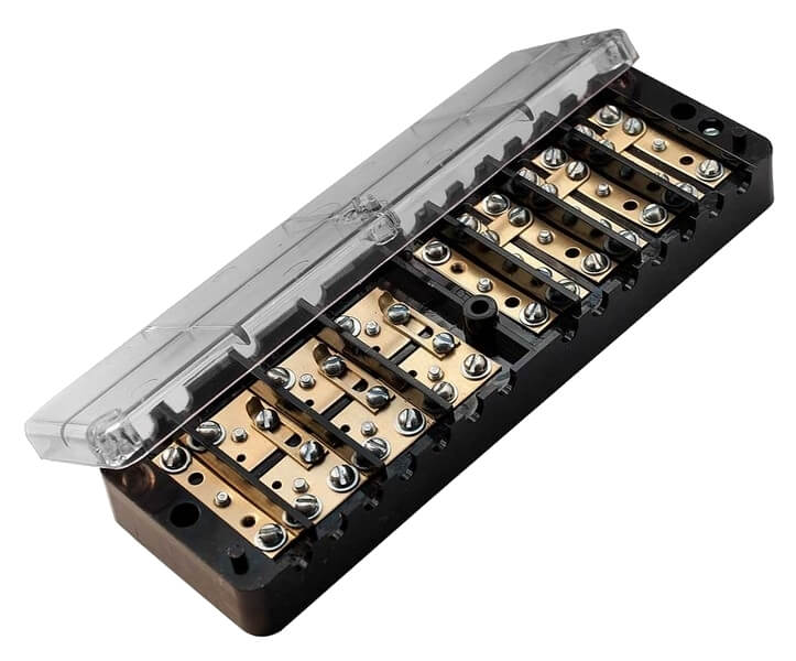
Typical adapter boxes are available in several versions, differing in their appearance and shape. Most often they look like a rectangular block with thick walls, made of durable and non-combustible material (carbolite or plastic). In this design, the box resembles a substrate with groups of terminals placed on it, forming a so-called "clamping cage".
Through holes are made along its edges, which are used to attach the IKK to the walls of the switchboard. Its connecting contacts are made on the basis of brass or galvanized steel (sometimes phosphor bronze is used for this). Some models of boxes are equipped with such additional elements as a flange or a lever, which simplifies the installation process.
Transitional contacts are made in the form of spring-loaded plates or screw clamps, placed on conductive plates made of brass, tin or steel. Their use is due to the resistance of these materials to corrosion and high conductivity. From above, the block is closed with a transparent plastic cover that is securely fixed to the base. When the test fixture is used in conjunction with an electric meter, its cover is also sealed. To do this, it provides through lugs for hanging a seal or a small hole for a control screw (screw). The transparency of the protective coating allows you to visually control the disconnection of the contact groups.
Typical differences
All test terminal boxes are primarily distinguished by the type of mains supply. In accordance with this indicator, they are divided into the following types:
- pads installed in 380 Volt power circuits;
- the same products, but designed for 220 volts;
- low-voltage samples intended for installation in a 110-volt network.
Products are usually distinguished by their shape and working dimensions. According to these characteristics, they can be round, rectangular or square, small in size or in an enlarged series.
In general, test boxes are classified according to the following characteristics:
- appointment;
- installation method;
- the number of rows on the substrate;
- the number of contact groups in each of them;
- type of fixation and brand of wire;
- execution (corner boxes or straight).
According to their intended purpose, the products are used together with meters or are intended for normal switching operations. They can be mounted on a DIN rail or installed in a cross-module. The possible number of rows and contact groups in these devices is one or two with the number of contacts from 3 or more.
In accordance with the method of fixation used, all boxes are available for screw, barrier and fixed (push) fixing. The brand of the connected wire is selected depending on the type of terminals used in the box. Screw and end fasteners are suitable for all types of conductors, while spring and knife clamps usually accept their single-core counterparts. However, the main difference between test blocks for meters is in the connection scheme, according to which they are used for one meter or for several samples at once.
IKK test boxes are produced by most of the major manufacturers of electrical equipment, using various materials in their manufacture. This fact is confirmed by the presence of various quality certificates for a number of products.
Mounting the device
The devices are in demand when laying new electrical lines and, if necessary, modernizing them. During installation, the requirements of the PUE regarding the rules for operating the test boxes must be met. According to the standards, for the placement of the KIC, it will be necessary to prepare a specially equipped place, protected from the penetration of unauthorized persons and accessible to service personnel.
At the terminals of the box, it is allowed to combine only wires made of homogeneous metals that have electrochemical compatibility.
The tightening torque of the contact screw connections should not exceed 2.5 Nm, which guarantees the safety of the terminals. In addition, they must be free from damage and obvious defects. Fixation of the IKK case at the installation site is carried out only mechanically - by screwing it or securing it using special latches. The box is usually installed in an electrical cabinet immediately after the electricity meter.
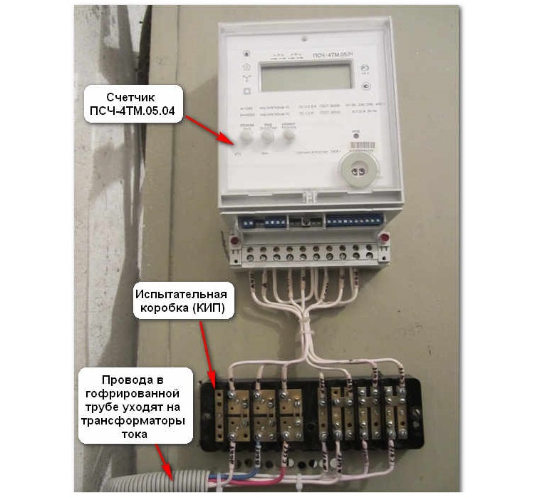
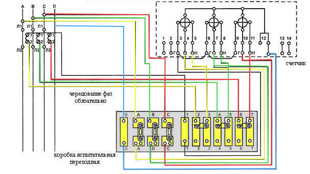
Connection example
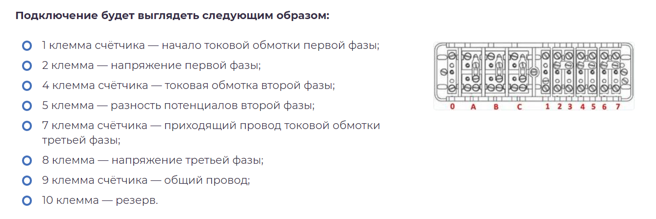
The connection of a real metering device (TsE6803 V100 / 10 T1, for example) by means of a test box is carried out according to a previously prepared scheme.
According to the PUE, all three-phase meters must be connected through current converters and an adapter box combined with them.
When choosing transformers, it is more convenient to use the TOP-0.66 product with a current transfer ratio of 200/5. As an example of connection, consider the box KI 10 or B3179, manufactured by METZ. Weight does not exceed 0.6 kg, dimensions - 68x220x33 mm. The sequence of disconnecting these products:
- The meter is mounted in the operating panel, and then the test box itself and current transformers.
- TTs for each of the phases are combined according to the "star" scheme; in this case, the common terminal is reliably grounded.
- From it to the box body, wires with a cross section of 1.5 mm² are stretched.
- Three conductors (2.5 mm²) are also laid from the meter.
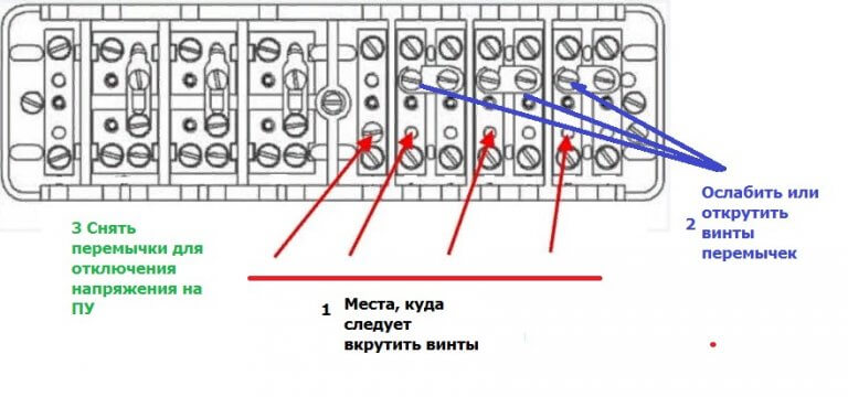
The disconnected test plate is closed with a lid on top, after which the product is ready for use.
If it is necessary to carry out any operations with the electric meter, to remove it, you only need to remove the jumpers in the IKK. After that, the chain of its connection with the metering device is broken.
Nuances of use
Test boxes, as the simplest type of construction, do not require special maintenance, which does not mean their absolute reliability. According to the requirements of the current standards, during the operation of the IKK, it is recommended to regularly tighten the contacts of the screw terminals. During operation, the conductors heat up and slightly deform, which causes the connections to loosen.
For boxes with crimp-type contacts, such requirements are usually not imposed. In addition, it is much more convenient to handle them, since no additional tool is required to turn off the meter.
The procedures related to installation, dismantling, as well as opening and subsequent sealing of the box are carried out only by qualified specialists.