Voltage stabilizers prevent damage to equipment and household appliances from load fluctuations. The device is compatible with single-phase and three-phase networks, suitable for apartments and private houses. A voltage stabilizer circuit may be needed when connecting the device yourself or arranging the electrical network.
- The principle of operation of stabilizers
- The principle of operation of relay models
- How Servo Drives Work
- The principle of operation of inverter devices
- Features of the calculation of characteristics
- Circuit for compensation stabilizer
- Serial circuit
- Parallel circuit
- Parametric stabilizer circuit
- Pulse device specifics
- Stabilizers on microcircuits
- Serial stabilizers
- The specifics of the parallel stabilizer
- Features of devices with three terminals
- Algorithm for self-assembly of the device
- Stabilizer connection diagram
The principle of operation of stabilizers
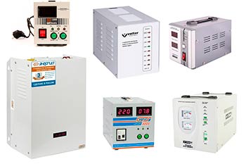
The principle of operation depends on the type of equipment. To highlight general points, it is advisable to consider the design. The device consists of the following elements:
- Control system. Allows you to monitor the output voltage, bringing it to a stable indicator of 220 V. The equipment operates with an error of 10-15%.
- Automatic transformer. Available for relay, triac, servo-motor versions. Raises or lowers the voltage rating.
- Inverter. Inverter models are equipped with a mechanism from a generator, transformer and transistors. Elements through the primary winding can pass or turn off the current, forming a voltage at the output.
- Protective block, secondary power supply. Available for 220 Volt models.
The bypass or transit function allows the regulators to supply voltage to the output until the set limit is crossed.
The principle of operation of relay models
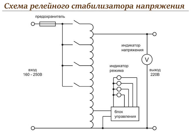
With its low cost and compactness, relay equipment slowly reacts to voltage surges, can turn off for a short time, and cannot withstand overload.
The device error is 5-10%.
How Servo Drives Work
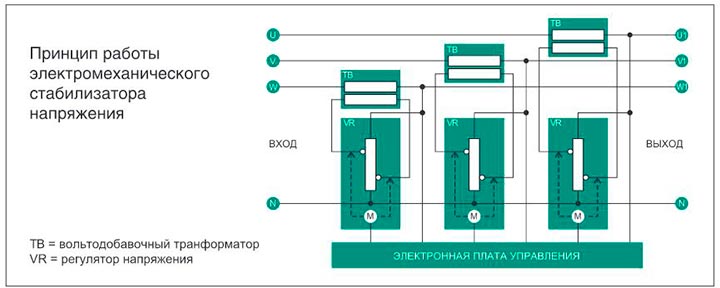
Servo-driven stabilizers can regulate the load of a three-phase and single-phase network. They are distinguished by their durability, reliability, and proper functioning during overload.
The accuracy of the instruments is 1%.
The principle of operation of inverter devices
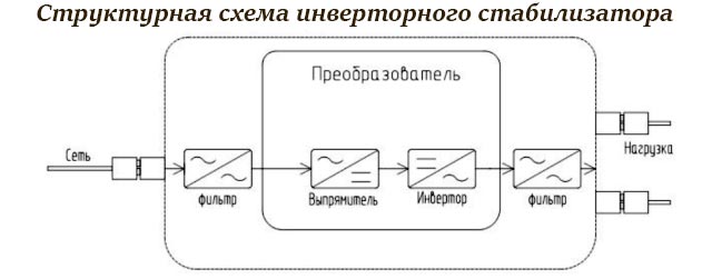
- The alternating current at the input is equalized, passed through a ripple capacitor filter.
- The rectified current is fed to the inverter, transformed into alternating current and fed to the load.
The output voltage remains stable.
Devices with inverters are characterized by quick response, efficiency from 90%, uninterrupted and silent operation in the range of 115-300 Volts.
The control range of the apparatus decreases as the load increases.
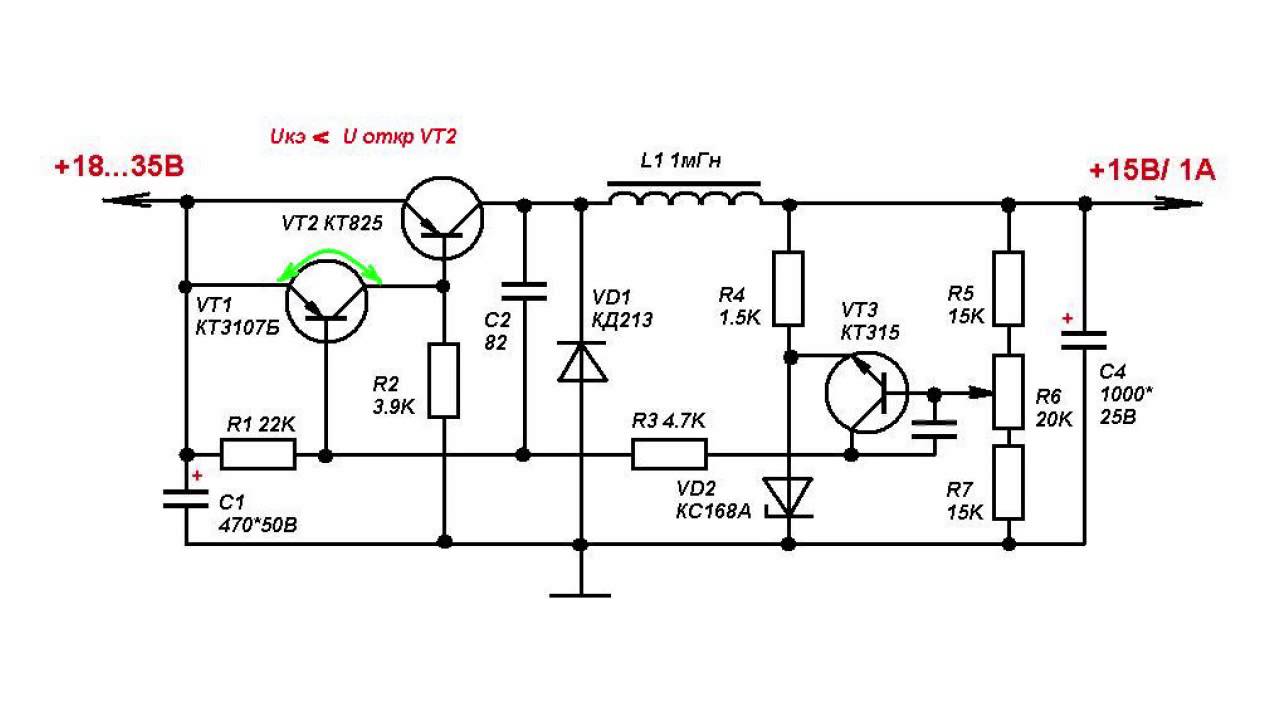
Features of the calculation of characteristics
 To install a parametric device, you need to calculate the power, input voltage, base current of the transistors. For example, the maximum output voltage is 14 V, the minimum output is 1.5 V, and the maximum current is 1 A. Knowing the parameters, the calculation is made:
- Input voltage. The formula is used Uin = Uout + 3... The figure is the voltage drop coefficient in the section of the transition from the collector to the emitter.
- The maximum power that the transistor dissipates. For selection in favor of a larger value, a reference book is needed. The following formulas are applied:Pmax = 1.3 (Uin-Uout) Imax = 1.3 (17-14) = 3.9 W; Pmax = 1.3 (Uin-Uout1) Imax = 1.3 (17-1.5) = 20.15 W.
- Transistor base current. Calculations are made according to the formula: Ib max = Imax / h21E min. The last indicator is 25, therefore 1/25 = 0.04 A.
- Parameters of the ballast thyristor. The formula is applied Rb = (Uin-Ust) / (Ib max + Ist min) = (17-14) / (0.00133 + 0.005) = 474 Ohm. Ist min - stabilization current; Ust - stabilization voltage, which is given by the zener diode.
Figures and calculations are provided for 1 ohm resistors.
Circuit for compensation stabilizer
Compensation circuits explain the feedback connection. The devices themselves have an accurate output voltage without reference to the load current.
Serial circuit

By designations from the reference book you can identify:
- regulating unit - P;
- source of reference voltage rating - AND;
- compared indicators - ES;
- constant current amplifier - W.
To calculate the output voltage, you need to know the features of the device. One transistor will regulate, and the other will stabilize. Zener diode is a reference source. The power difference is the voltage between the emitter and base.
When the collector current is applied to the resistor, the voltage drops, has reverse polarity for the emitter assembly. The result is a drop in the collector and emitter currents. To make the adjustment smooth, a divider is used for the stabilizer line. The step regulation is achieved using the voltage of the Zener diode support.
Parallel circuit

If the voltage deviates from the nominal, a mismatch pulse occurs. This is the difference between yield and support rates. Since the control unit is parallel to the load, it amplifies the signal. There is a change in the current at the regulator element, a drop in the voltage of the resistor and a constant value at the output.
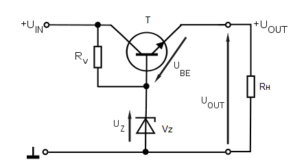
Parametric stabilizer circuit
The diagram explaining the process of stabilizing the reference voltage will be the main one for parametric models. The voltage divider of the device is a ballast resistor and a zener diode with a parallel load resistance. When the nominal supply voltage and current load fluctuate, the voltage is stabilized.
If this indicator increases at the input, the current passing through the zener diode and resistor increases. Thanks to the volt-ampere indicators, the zener diode rating remains almost unchanged, as does the voltage of the load resistance. All vibrations concern only the resistor.
Pulse device specifics
The impulse device is characterized by high efficiency even in conditions of a large voltage range. The device circuit includes a key, an energy store and a control circuit. The adjustment element is connected in pulse mode. The principle of operation of the device:
- A positive feedback voltage is supplied from the second collector through the second capacitor to the base.
- Collector # 2 opens after current saturation from resistor # 2.
- At the junction from the collector to the emitter, the saturation is less, and it remains open.
- The amplifier is connected to the collector # 3 through the Zener diode # 2.
- The base is connected to the divider.
- The first zener diode controls the opening / closing of the second collector by a signal from the third.
When the second zener diode is open, energy is stored in the choke, supplying the closing field to the load.
Stabilizers on microcircuits
A linear divider is distinguished by the supply of an unstable voltage to the input and the removal of a stable voltage from the divider arm. Alignment is carried out by a pitch arm that maintains constant resistance. The devices are distinguished by their simplicity of design, absence of interference in operation. Microcircuits are connected in series or in parallel.
Serial stabilizers
Series devices are characterized by the inclusion of a control element in parallel with the load. There are two modifications:
- With bipolar transistor. It does not have an autoregulated circuit, voltage stability depends on the magnitude of the current and temperature indicators. An emitter follower or a composite transistor is used as a current amplifier.
- With auto-adjustment loop. The compensating device works on the principle of equalizing the output and reference values. Part of the output voltage is removed from the resistive divider, and then compared using a zener diode. The control loop is a 180 degree feedback loop. The current is stabilized by a resistor or power supply.
The most popular series stabilizers are integral ones.
The specifics of the parallel stabilizer
A parallel device is distinguished by the inclusion of a control element parallel to the supplied load. The zener diode is used of a semiconductor or gas-discharge type. The circuit is in demand for regulating complex devices.
Reducing the unstable voltage at the input is carried out using a resistor. It is allowed to use a bipolar machine with high differential resistance values in a separate area.
Features of devices with three terminals
Stabilizers for alternating voltage are small in size and are available in a plastic or metal case. They are equipped with channels for input, ground and output. The capacitors of the device are sealed on both sides to reduce ripple.
The output voltage is about 5 V, the input voltage is about 10 V, the dissipation power is 15 W.
Three-pin modifications make it possible to obtain a non-standard voltage required for powering breadboards, low-power batteries, when repairing or upgrading equipment.
Algorithm for self-assembly of the device
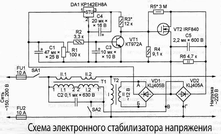
For self-production, it is advisable to use a triac circuit - an effective device. It equalizes the rating of the supplied current at a voltage from 130 to 270 V. The device can be made on the basis of a printed circuit board made of foil textolite. The assembly of the device is carried out as follows:
- Preparation of the magnetic core and several cables.
- Creating a winding from a wire with a diameter of 0.064 mm - 8669 turns will be needed.
- The remaining conductors with a diameter of 0.185 mm are needed for the remaining windings. The number of turns of each is 522.
- Series connection of 12 V transformers.
- Organization of 7 branches. The first 3 are made from wire with a diameter of 3 mm, the others - from tires with a cross section of 18 mm2. So the homemade device will not heat up.
- Installing a controller chip on a platinum heatsink.
- Installation of triacs and LEDs.
The device will need a sturdy case attached to a rigid frame. The easiest option is polymer or aluminum plates.
Stabilizer connection diagram
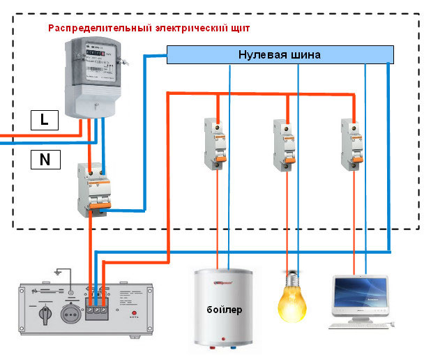
The stabilizer is entered into a private house using a three-core VVGng cable, a three-position switch and a PUGV wire. Installation is carried out before the meter, in a separate or distribution board:
- Open the contacts by lifting the front cover.
- Pass the cable to the exit and entrance. Tighten the input phase to the Lin terminal, the neutral (blue) conductor - to the Nin terminal, the ground - to the screw terminal with the corresponding designation.
- If there is no ground, tighten this core under the screw on the device body.
- Return the stabilized voltage to the common shield. Phase is applied to the Lout output, zero to Nout, and ground to ground at the input.
- Test the circuit in no load mode.
For the test, all machines are turned off, except for the input and directed to the stabilizer.
The stabilizer connected between the mains and the load is suitable for a private or country house, apartment, production. The device protects equipment from failure, eliminates the effect of overload and short circuits on the power line.