The flow resistance in the manifold acts on the structure of the pipeline in the places of narrowing and expanding the diameter, connecting and turning nodes, due to which pressure in the pipeline is lost. The hydraulic calculation of the pipeline is carried out at the design stage to ensure the normal operation of consumers and the supply of the required volume of gas.
- Definition and necessity of hydraulic calculation
- Basic source data
- Calculation schemes
- Methodology
- Influence of pipe material on calculation
- Special programs
- Professional
- Free of charge
- Free online programs
- Examples of performing a hydraulic calculation of a pipeline
- Low pressure gas pipeline calculation
- High pressure gas pipeline calculation
Definition and necessity of hydraulic calculation
Resistance includes linear obstruction along the entire length and local obstructions at each structural element of the system in the area of speed change. Hydraulic calculation determines the parameters of the gas pipeline. The procedure is a mandatory step in the preparatory stage for the construction of the pipeline.
As a result, a pipe diameter is accepted that is acceptable for highly stable transmission of gas over a distance. The calculation determines the amount of head losses and their admissibility when transferring fuel.
State norms regulate the calculation procedure for any types of gas pipeline systems, since the processes when supplying gas are characterized by identity.
The pipelines are checked for pressure loss:
- low pressure;
- medium head;
- high.
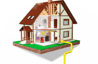
Low-pressure highways transport fuel to residential buildings, household enterprises, social significance, the pressure at the level of 3-5 kPa is considered normal. High and medium pressure highways include branches for mass deliveries, industrial networks, general pipelines for regions and cities.
Basic source data
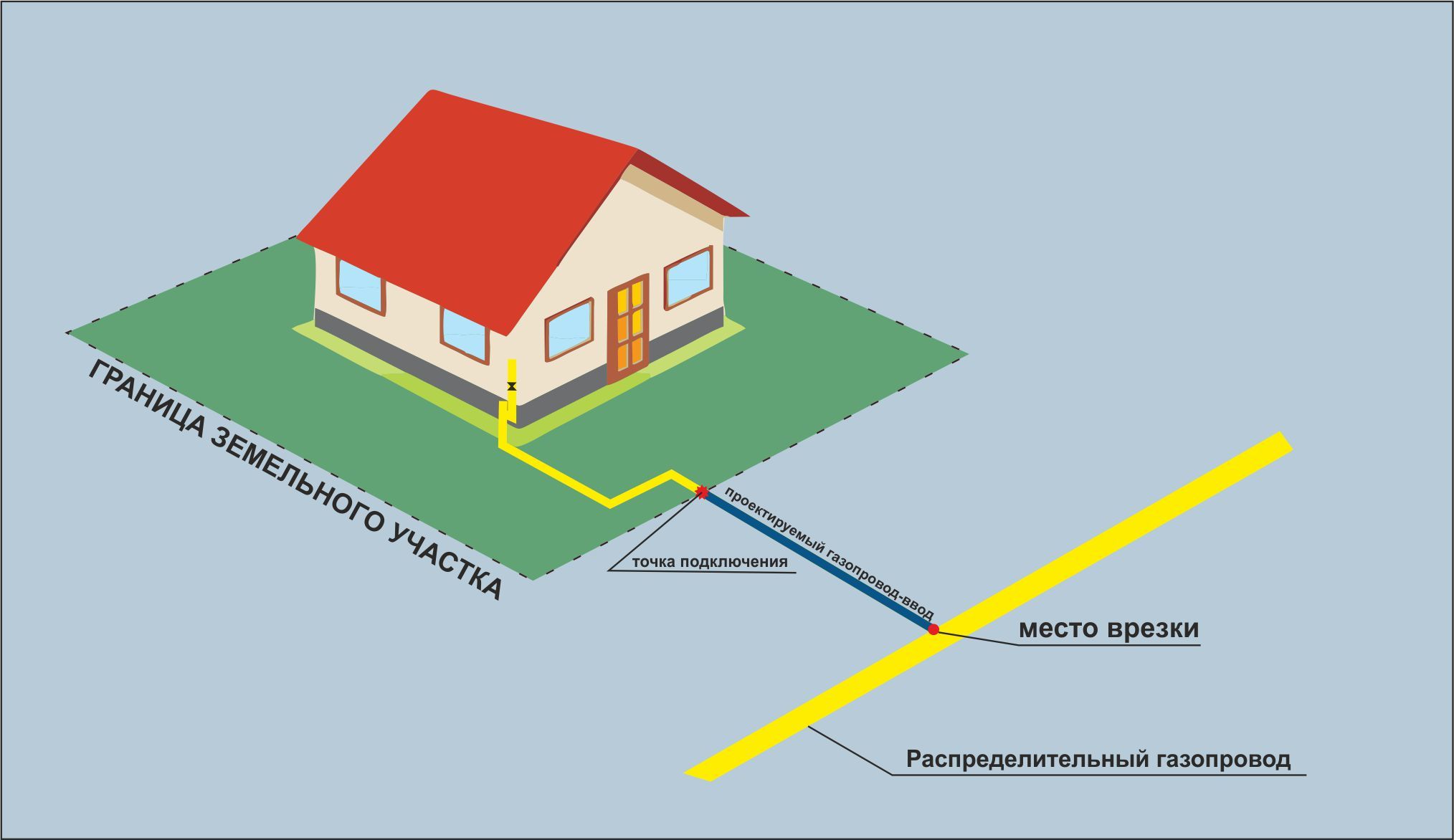
The initial parameters depend on the gas pipeline scheme, which can be mixed, ring and dead-end. The pressure in the network decreases with distance from the point of tapping or distribution.
Initial parameters are presented by information:
- head in the place of the tie-in;
- customer details such as number, location, required nominal flow rate and pressure;
- gas pipeline diagram.
Dead-end areas branch off from the main one to consumers and refer to areas with low reliability and difficult recovery in case of an accident, but require less installation costs. The ring system works more reliably, but installation requires increased costs.
Calculation schemes
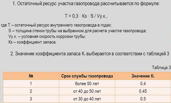
The pressure is determined taking into account the diameter of the pipes, taking into account the influence of internal corrosion, the material of the collectors, the geometric shape of the section. The pipe shells fail when the wall stress reaches the permissible tensile strength.
During the hydraulic test, a liquid with a temperature of +5 to + 40 ° C is used, unless the technical task for the test recommends another parameter. When calculating the strength, the temperature of the test and the environment does not drop less than + 5 ° C.
The holding time under the design pressure is indicated by the designer, but it is always taken more than 5 minutes. In the absence of recommendations, the duration of the high pressure is established according to the standard tables and depends on the thickness of the pipe shell.
Methodology
The procedure for choosing the diameter and design scheme of a low-pressure gas pipeline is given in the profile Code of Practice 42. 101 - 2003. Computer programs are used to find the value of the estimated pressure loss between the pipeline sections, the diameter of the collectors.
Methods are applied:
- calculation by formulas from the joint venture (complex process);
- the calculation according to nomograms is easier, the technique of selection according to tables with the substitution of the required parameters is used.
Any technique leads to the same results to ensure uninterrupted transportation of gas fuel to consumers.
Influence of pipe material on calculation
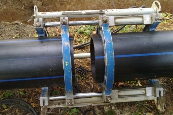
Gas pipelines are built from steel, polyethylene, copper is used in critical areas. Reinforced-plastic structures are conquering the consumer market. The information in professional tables and collections applies only to plastic and metal pipes, therefore calculations are carried out for highways made of such materials.
Gas supply pipes are calculated taking into account the roughness coefficient:
- polyethylene (new and old) - 0.007 cm;
- steel, used - 0.1 cm;
- new metal - 0.01 cm.
If the pipeline is made of a different material, gas experts will not accept the calculation for metal and plastic, an adjustment will be required, which will entail additional costs.
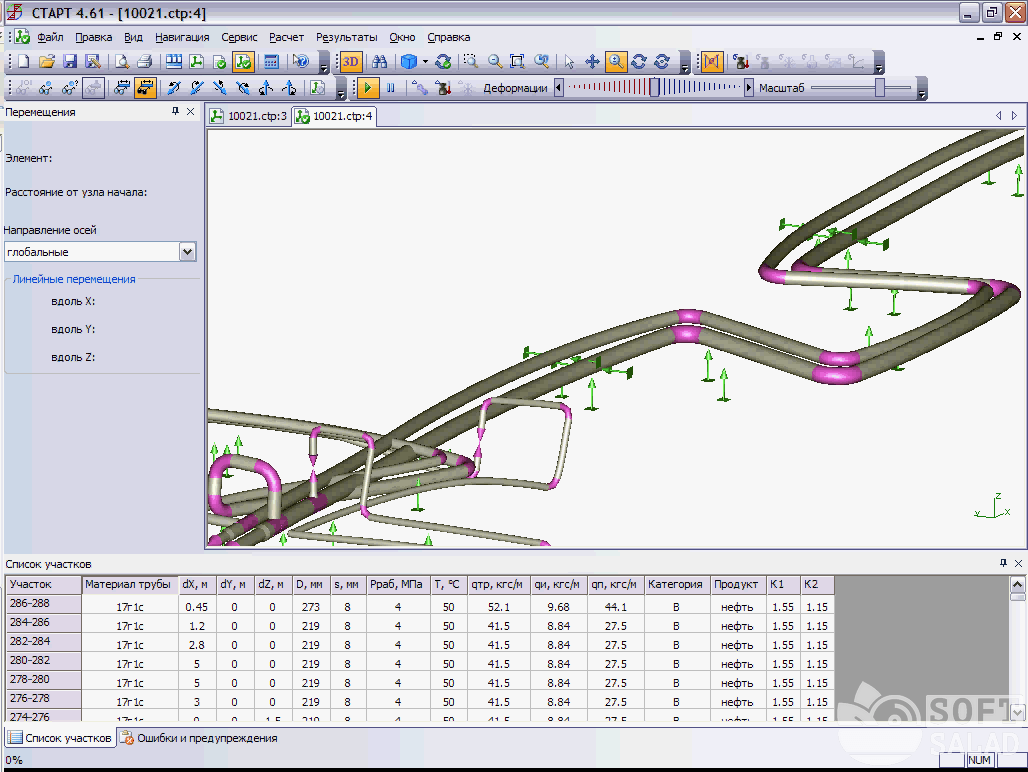
Special programs
Branched sections of a gas pipeline with different initial data are calculated separately, but the procedure is carried out in the same way for each area. The flow velocity changes in places of resistance and changes in direction of movement. Linear indicators are calculated on the calculated lengths of the line sections.
The direction is chosen depending on the difference in pressure at the end and at the beginning of the studied area. The flow goes from a point with more pressure towards a place with less resistance. Programs help reduce the effort of designers by having initial values entered into the program and the electronics doing the calculations.
Nomograms are designed to summarize information using tables, where each row corresponds to the specified network parameters.
Professional
Professional calculation implies not only the use of formulas and numerical expressions, but also the possession of special knowledge. Skills will not come in handy when using free calculation programs that can be found on the Internet.
Free of charge
Programs are installed for use on personal gadgets. The methods determine the diameter, cross-sectional shape of the gas pipeline, taking into account the permissible losses and flow rate. The user will need the total gas consumption, which is given in the technical documents for the boiler, gas stoves, water heaters and other equipment.
Then the places with a possible decrease in pressure are determined. Characterizing figures are in the passport table, they show a decrease in pressure at the highest consumption. The amount of drop at the infeed point is found. The coefficient of simultaneity takes into account the combined operation of devices and is contained in the tables.
The pipe diameter and roughness factor are specified at the last stage. The program provides for dissimilar calculations for different pressures in the pipes, which must be taken into account when including the data.
Free online programs
In this case, the user substitutes the required information in the columns of the table for online calculations.The hydraulic calculation of a low-pressure gas pipeline takes several minutes and no professional knowledge and computational skills are required from the consumer.
Data is taken from the technical conditions:
- the density of the gas mixture;
- kinetic viscosity index;
- climatic temperature range of the region of residence.
Technical conditions are issued by the gas service of the settlement, the preparation of project documentation begins with the receipt of this assignment.
Examples of performing a hydraulic calculation of a pipeline
The exact number of hotplates of the connected equipment is given to select the simultaneity factor. The numbering of the pipeline sections is not chosen arbitrarily, but is taken from the technical diagram.
The actual length of the line is indicated and the calculated length is indicated, which is greater. When calculating, this parameter increases by 7% due to the presence of areas of resistance. The table indicates all structural elements of the pipeline, where the pressure loss is assumed.
Low pressure gas pipeline calculation
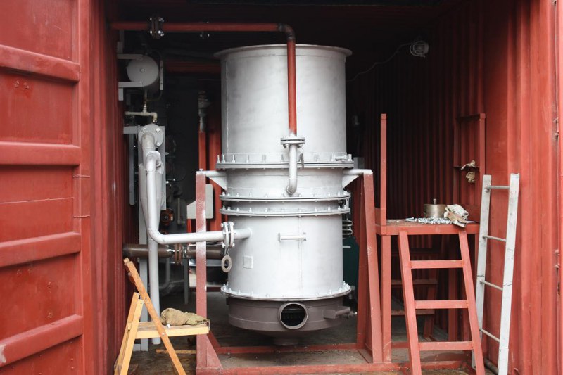
When calculating the gas pipeline inside the house, the amount of boiler equipment is multiplied by the output of each unit. The result obtained is multiplied by the indicator of the simultaneous operation of the units, which is determined from the corresponding table in the reference book.
The number of plates in all apartments is multiplied by the productivity of each, the product of the result obtained and the coefficient of simultaneity for the connected devices is found. Finally, the total pressure for the heating units and the connected gas stoves is summed up.
High pressure gas pipeline calculation
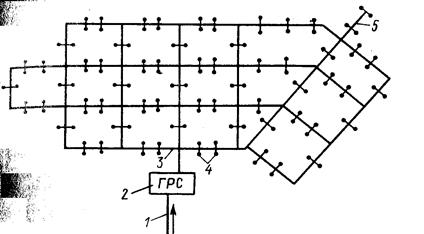
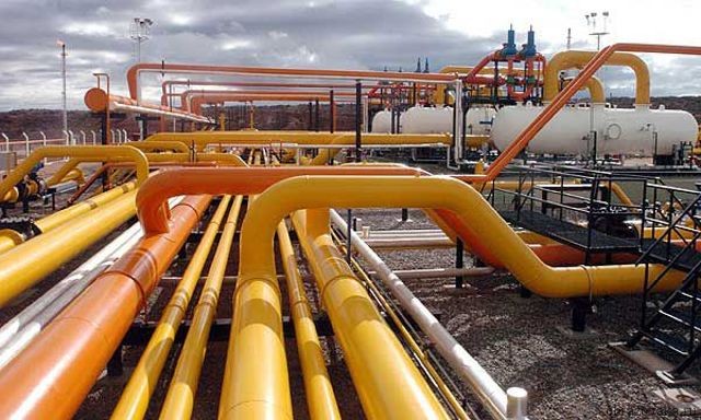
The calculation is made on the basis of the distribution scheme, taking into account the branches to the consumer areas. The source of separation is the gas distribution substation. The diameter of the common gas pipeline and branches is based on the gas pressure at the end of the path when entering the consumer.
The calculated length of each branch is determined, the pressure is found taking into account losses and resistance in some places. Dead-end sections are considered according to their length, gas consumption and the estimated fuel pressure at the point of connection to the consumer.
The calculation is considered satisfactory if the calculated values of the consumer pressure do not exceed the head of the network.