The design of ventilation systems allows you to plan the scope of work and future costs at the initial stage. According to the specification of the equipment, an estimate is made for the construction of the facility. Despite the fact that the design of ventilation for industrial premises or private houses is quite costly, without it, the construction of a large building is impossible.
An apartment ventilation project is ideally created at the stage of designing the building itself or planning a major overhaul. Then there is an opportunity to optimally distribute the equipment, build it into existing engineering communications, and accurately fit it into the interior design.
The design of supply and exhaust ventilation takes place in several stages:
- Calculation of equipment and communications. It is produced based on the parameters of the premises and the requirements for the microclimate.
- Drawing up wiring diagrams.
- Drawing up the final project.
The work is carried out after the conclusion of a contract for the design of ventilation with an exact indication of the delivery time and cost.

When concluding a contract, the customer can be provided with samples of technical specifications for the design of ventilation or ready-made projects for review.
There are standard apartment ventilation projects that can be used for installation and significantly save money.
- Terms of reference for the design of ventilation
- Calculation of the ventilation project
- Standard equipment selection schemes
- Air preparation for ventilation design
- Air distribution in ventilation design
- Airway parameters
- Smoke ventilation design
- Ventilation design for clean rooms
- Air movement in clean rooms
- Wiring diagram for designing ventilation
- The final stage of ventilation design
- Ventilation design terms
Terms of reference for the design of ventilation

To draw up a technical task, it is not enough to know only the basics of ventilation design. The task indicates the parameters of the microclimate, the method of air exchange, data on the coolant.
Drawing up the terms of reference for the supply ventilation project precedes the analysis of the layout and purpose of the building. Therefore, the designer must provide the most complete data:
- the purpose of the object;
- location (including relative to parts of the world);
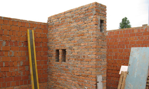
- properties of building materials;
- glazing area and number of doors;
- floor plans and sections;
- information about the coolant.
When designing industrial ventilation, it is necessary to delve into the intricacies of the technological process, as well as the work schedule (for industrial facilities). The terms of reference also take into account the special wishes of the customer.
Calculation of the ventilation project
When designing supply and exhaust ventilation, calculations are made for the best technological and economic selection of equipment, the shape of the route and the parameters of the air ducts.
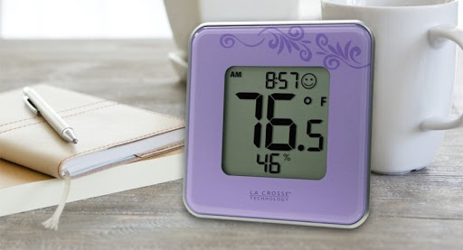
The calculation of the microclimate in the premises is made for cold, transitional and warm seasons. Environment parameters are determined by SNiP 23-01-99 and 41-01-2003.
The calculation of air exchange is determined on the basis of the air exchange rate approved in the normative documentation. When determining the frequency of air exchange, heat inflows and the number of people constantly in the premises are taken into account.
Air exchange rate for premises, depending on the purpose
| Apartment, private house | 4-8 |
| Office | 4-8 |
| Kitchen | 15-30 |
| Entertainment Center | 4-6 |
| Score | 3-8 |
| Server | 6-10 |
| Pool | 5-6 |
| A restaurant | 7-12 |
Volume of supplied air for 1 person in cubic meters / hour
| Apartment, private house | 25-60 |
| Office | 35-60 |
| A restaurant | 45-60 |
| Kitchen | 65-90 |
| Entertainment Center | 35-60 |
| Score | 25-60 |
| Swimming pool, sports complex | 80 |
The type of air exchange is selected taking into account the purpose and architecture of the room, the ability to organize natural air exchange.
Depending on this, the system is selected:
- supply;
- supply and exhaust;
- exhaust;
- local;
- general exchange;
- natural;
- mechanical.
The equipment is selected depending on the purpose of ventilation, building architecture, economic benefits and types of coolant. A standard selection scheme can be used or an individual one if the standard one is not suitable for technological or economic reasons.
Standard equipment selection schemes
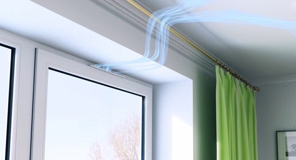
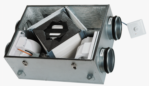
- When designing ventilation for an apartment, small shop or office, natural ventilation is usually provided, enhanced in kitchens and toilets with exhaust fans. The air supply is supported by compact supply units or ventilators. It is also advisable to install ducted air conditioners or supply and exhaust systems;

pool ventilation scheme When designing the exhaust ventilation of a pool or sauna, supply and exhaust systems are provided in combination with a dehumidifier. Some compact air handling units are also equipped with dehumidifiers;
- When designing a ventilation system for a cafe or restaurant, two installations are laid at once: general exchange and local. For a small cafe, a compact ventilation system is sufficient. Large catering establishments are supplied with powerful hoods for kitchens and type-setting inflow-blowing units for the dining area;
- The design of the supply and exhaust ventilation of a sports complex provides for intensive air exchange with the possibility of air conditioning;
- Ventilation of high-rise buildings, shopping and entertainment complexes, public buildings is carried out by central, roof and autonomous air conditioners, chiller-fan coil units;
- Industrial ventilation design should implement more complex and specific tasks. Therefore, the equipment is selected for each object individually. As a rule, if the technological process is accompanied by an abundant release of heat and toxic fumes, local and general exhaust systems are combined. Suction units, oases and air showers are used as local devices. When designing ventilation of industrial premises with abundant emission of dust, explosive and toxic substances, aspiration systems are provided.

Air preparation for ventilation design
When designing ventilation for a private house, shop or factory, the need to filter the supply air, and often also the removed air, is taken into account.
General Purpose Filter Classification
| Filter group | Class | Efficiency | Notes (edit) |
| Preliminary (G) | 1 | Up to 65% | The action is calculated from a suspension with large particles (from 2 micrometers) |
| 2 | 65-80% | ||
| 3 | 80-90% | ||
| 4 | More than 90% | ||
| Fine cleaning (F) | 5 | 40-60% | The action is calculated from a suspension of particles up to 1 micrometer |
| 6 | 60-80% | ||
| 7 | 80-90% | ||
| 8 | 90-95% | ||
| 9 | More than 95% |
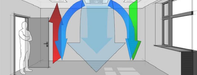
Air distribution in ventilation design
Air distribution is possible in two ways:
- crowding out;
- mixing.
In addition, the best way of air flow and its removal is determined:
- upper;
- lower.
Inflow type:
- flat jets;
- covering jets;
- fan-shaped;
- compact.
The number of air distributors and their type are counted.
Airway parameters
The cross-section and shape of the air ducts are calculated, the material for them, the shape, the number of branches and turns, pressure losses, as well as the sound pressure at the entrance to the room are determined.
These indicators are directly related to the power of the equipment, the parameters of the silencers. And all together determines the price of the ventilation system.
Smoke ventilation design
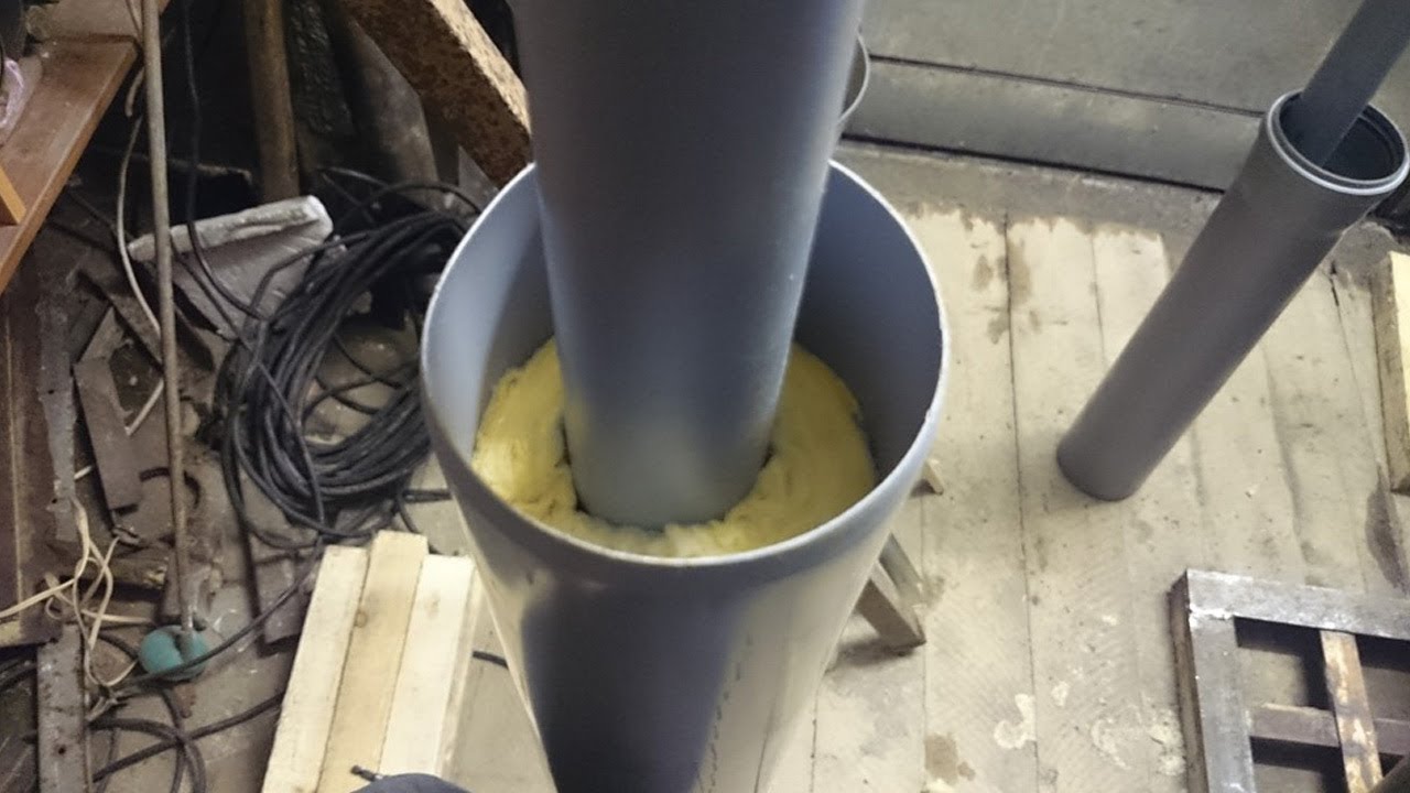
The task of the anti-smoke ventilation unit is to maximally block and limit the spread of smoke. An autonomous smoke control system is installed in each fire compartment. Smoke ventilation design adds significant cost and complexity to the system. It is necessary to purchase additional equipment, since many materials widely used in ventilation (for example, PVC air ducts) do not withstand the temperature.
The project of exhaust smoke ventilation provides for the use of only special fans and ventilation ducts that do not deform at high temperatures, fire dampers and smoke detectors.
Sometimes specially designed doors and smoke screens are installed.
As a rule, smoke ventilation is designed by computer programs. The program carries out all the necessary calculations, simulating the situations that arise during a fire. The rest of the work is carried out by the designers "manually".
The calculation is made for each room separately, taking into account leaks in ventilation ducts, fire valves, and the area of the smoke channel. To speed up the evacuation of smoke in long corridors, several smoke collectors are being designed. The exact number of them depends on the area of the room.
For a straight corridor no more than 45 meters long, 1 receiving device is sufficient. If there are turns, 1 device is installed for every 30 meters. Limited sections of the corridor must not exceed 20 meters in length.
Since the development of the situation during a fire is simulated by a computer, it is impossible to verify the accuracy and correctness of the calculations. Therefore, the experience and qualifications of the designer are required for the laying of the airway and smoke exhaust ducts. Smoke ventilation is not used for air intake. It only removes smoke without connecting to the general air exchange system. The smoke exhaust system starts only during a fire. The rest of the time, it is periodically checked for operability.
In a one-story private house, it is allowed to design natural draft smoke ventilation.
Standard conventions are used when designing smoke exhaust ventilation.
Ventilation design for clean rooms
The main difference between the design of clean rooms and premises for other purposes is the need to use HEPA filters H11-H14. HEPA filters create high resistance both at the beginning of use - up to 350 Pascals, and at the end before replacement up to 650 Pascals. This feature must be taken into account when calculating air flow rates. The resistance of the filters must be compensated.
Filter classification for special purposes
| Filter group | Class | Efficiency | Note |
| High efficiency (H - HEPA) | 10 | 85% | The filter efficiency is calculated based on the presence of dust with particles of 0.1 - 0.5 micrometers in size. |
| 11 | 95% | ||
| 12 | 99,5% | ||
| 13 | 99,95% | ||
| 14 | 99,995% | ||
| Ultra High Efficiency (U) ULPA Filters | 15 | 99,9995% | |
| 16 | 99,99995% | ||
| 17 | 99,999995% |
When designing ventilation for clean rooms, the main attention is paid to:
- increased tightness of fences;
- the device of the vestibule-gateway;
- selection of HEPA filters.
In clean rooms, the pressure must be positive. If this value is exceeded, a decrease in tightness is possible due to deformation of the fences. Therefore, the magnitude of the pressure must be strictly controlled.
When the airlock is opened, the excess pressure decreases and can equalize with the surrounding rooms. Then dust can enter the room through the doors.
When designing ventilation in clean rooms, air exchange is often expressed in terms of air mobility, which should be from 0.35 to 0.51 meters per second.
The air change should be within 30 - 60 times, sometimes with a moderate degree of purity it is allowed to decrease the value up to 20 times. An error of 20% is allowed.
Maximum speed is required when employees are very active and dust-generating equipment is present. If there are few personnel in the room, the work is sedentary, and the equipment does not emit dust, the minimum speed values are sufficient.
Air movement in clean rooms
After cleaning in special filters, the air enters the premises practically without dust.
In this case, the air supply performs two tasks:
- Reducing the concentration of dust that appears in the room during the presence of personnel and equipment operation.
- Evacuation of this dust from the premises.
There are 3 types of air movement in rooms:
- Unidirectional ordered or laminar. Air jets move in one direction parallel to each other.
- Disordered or turbulent. Air jets do not move parallel to each other.
- Mixed. In part of the hall, laminar is organized, and in the other - turbulent.
In cleanroom projects, only systems of unidirectional ordered air movement are included. For this, air is supplied through filters placed over the entire surface of the ceiling. The floor is made perforated and an exhaust chamber underneath. Air ducts are run between the exhaust chamber and the filters for air recirculation.
According to the basics of ventilation design, if the width of the clean room is less than 5 meters, it makes sense to design exhaust grilles in the lower part of the wall instead of a raised floor. The air moves vertically up to a height of 0.5 above the floor level and then turns to the gratings.
In clean rooms of medium regime, turbulent air movement is often organized. HEPA filters are placed on the ceiling, in general, the flow is directed downward, but the individual jets are not parallel to each other.
Mixed air circulation is possible only if technological processes with increased and usual requirements for the content of dust in the air are combined in one hall. For zoning the room, filters are arranged on the ceiling in a special way. There are more filters in the "clean" zones, and fewer in the usual ones.
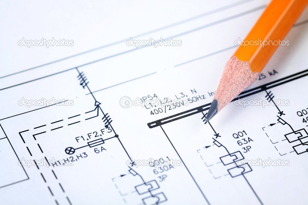
Wiring diagram for designing ventilation

The graphic wiring diagram of the ventilation system contains not only the drawing itself, but also a description of the type of ventilation, the parameters of the equipment and its location, the specification of equipment and materials.
Together with the diagram, a task for construction work on the preparation of sites for equipment and air duct routes is attached to the ventilation system project. A feasibility study is being prepared.
When creating a project for industrial or domestic ventilation, the equipment is placed in convenient places for servicing.
The final stage of ventilation design
The final project of ventilation of the production premises is handed over to the customer only after the complete installation of the equipment.
According to the contract, the ventilation project contains:
- symbols of materials and technology;
- exact dimensions and bindings;
- intersections, junctions and forks;
- location of equipment with axonometry;
- calculations with explanations;
- specifications;
- the main drawing of the system and drawings of additional subsystems, power grid, ventilation wiring, drainage, communications between modules, cooling circuits;
- executive wiring diagram.
During the design of exhaust ventilation, at each stage, coordination is carried out with designers, architects and other specialists who carry out finishing, construction and installation of engineering systems.
Ventilation design terms
Ventilation design time is on average 15 working days for the smallest buildings and is determined by the area of the facility. With an area of up to 300 square meters, a ventilation project is completed in a minimum time.
With an area of up to 1000 square meters, designing ventilation of the supply or supply and exhaust type takes up to 40 days.
The duration of the ventilation project of the facility is more than 2 thousand square meters. meters is determined individually.
Any design work, whether it is the design of ventilation of a private house or workshops of a confectionery factory, must be carried out by a qualified licensed specialist.
You will get answers to the most common questions about ventilation design from the videos: